Antenna, and radio-controlled timepiece, keyless entry system and RFID system using same

An electromagnetic wave and antenna technology is applied in the fields of antennas, electromagnetic wave watches using the antennas, keyless input systems and RFID systems, and can solve problems such as hindering electromagnetic wave reception.

Inactive Publication Date: 2007-01-10
PROTERIAL LTD
View PDF4 Cites 9 Cited by
  • Summary
  • Abstract
  • Description
  • Claims
  • Application Information

AI Technical Summary

Problems solved by technology

Such a keyless input system or RFID system also has the problem of blocking the reception of electromagnetic waves by the metal because it has a magnetic sensor antenna installed in the metal housing or near the metal parts.

Method used


Image

  • Antenna, and radio-controlled timepiece, keyless entry system and RFID system using same
  • Antenna, and radio-controlled timepiece, keyless entry system and RFID system using same
  • Antenna, and radio-controlled timepiece, keyless entry system and RFID system using same

Examples


Embodiment 1

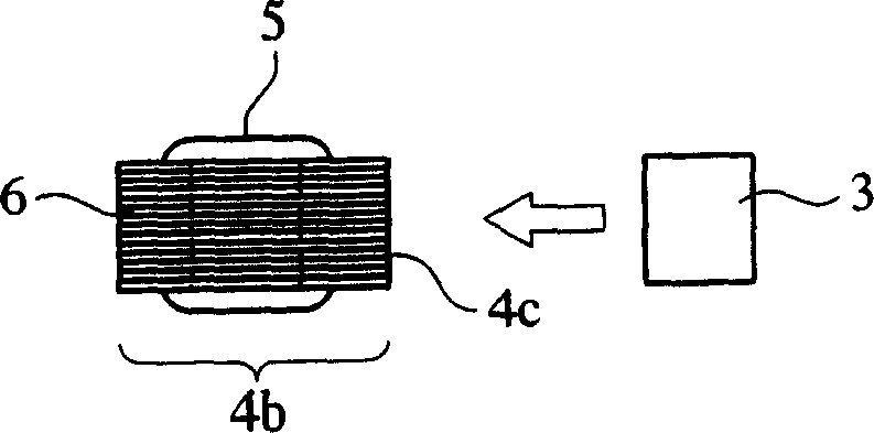
[0059] The antenna 1 having the main magnetic circuit member 2 and the auxiliary magnetic circuit member 3 shown in FIGS. 4( a ) and 4 ( b ) is manufactured as follows. The main magnetic circuit part 2 is made of Mn-Zn ferrite (specific magnetic permeability: 7000, ferrite MT80D manufactured by Hitachi Metals Co., Ltd.), and has a central part 4a (2mm x 2mm x length 8.4mm) and a cover The ends 4b and 4b on both sides (4mm×4mm×length 0.8mm) are processed into a magnetic core 4 and a coil 5 made of copper wire coated with insulating varnish with a wire diameter of 65 μm. The coil 5 is wound with 1180 turns. I wind it around the central part. 45% by volume of flat high-permeability nanocrystalline soft magnetic metal powder (refined pure metal (registered trademark) manufactured by Hitachi Metals Co., Ltd.) with a thickness of 1 μm and an average particle diameter of 35 μm was used as a binder resin ethylene methyl acrylate A thin slice (thickness: 0.13 mm) of a mixture (specifi...

Embodiment 2~4

[0064] An antenna was manufactured in the same manner as in Example 1 except that the thickness t of the sub-magnetic circuit member 3 was changed as shown in Table 1. In Example 4, such as Figure 11As shown, two secondary magnetic circuit members 3a, 3b each having a thickness of 0.5mm are attached to both sides of the end portions 4b, 4b of the magnetic core 4. As shown in FIG. The Q value, signal voltage S, noise voltage N, and S / N ratio were measured in the same manner as in Example 1. exist Figure 8-10 Indicates the result.


PUM


Abstract

An antenna of the invention comprises a magnetic main-path member comprising a coil wound around a magnetic core, and a magnetic sub-path member magnetically connected to the magnetic core for constituting a substantially closed magnetic path with the magnetic main-path member, the antenna meeting the relation of (S / N)1>(S / N)0, wherein (S / N)1 is a ratio of a signal voltage S obtained from the coil to a noise voltage N in this antenna, and (S / N)0 is a ratio of a signal voltage S to a noise voltage N in an antenna having the same structure except for having no magnetic sub-path member.

Description

technical field [0001] The present invention relates to an electromagnetic wave watch suitable for receiving electromagnetic waves including time information to correct the time, an intelligent keyless input system for unlocking a car or a house key by detecting the owner's approach with electromagnetic waves, and a modulation signal carried in electromagnetic waves. Magnetic sensor antennas in RFID tag systems for sending and receiving information, and electromagnetic wave watches, keyless entry systems, and RFID systems using the antennas. Background technique [0002] As a watch that corrects time by receiving electromagnetic waves including time information, it is practically used in various forms such as sitting clocks, wall clocks, and wristwatches. Electromagnetic waves in the long-wave band (40-200kHz) are usually used in electromagnetic wave watches. In particular, two frequencies of 40kHz and 60kHz are used in Japan, and frequencies below 100kHz are mainly used in ...

Claims


Application Information

Patent Timeline
Patent Type & Authority Applications(China)
IPC IPC(8): H01Q7/06H01Q7/08G04C9/02G04C11/02G04G7/02B60R25/01B60R25/24E05B49/00G04R20/00G04R20/08G04R60/12G06K19/07H01Q1/22H01Q1/44
CPCH01Q7/08H01Q1/44H01Q1/22
Inventor 荒木博和三俣千春三田正裕
Owner PROTERIAL LTD
Why Eureka
Try Eureka