
Stroke control device

A technology of stroke control and pressure release, which is applied in the direction of manufacturing tools, metal processing, presses, etc., can solve the problems of loss of control of the stroke switch, failure to prevent the rotation deviation of the piston rod, etc., and achieve the effect of ensuring normal operation

Active Publication Date: 2006-12-27
GUIYANG AL-MG DESIGN & RES INST
View PDF0 Cites 5 Cited by
  • Summary
  • Abstract
  • Description
  • Claims
  • Application Information

AI Technical Summary

Problems solved by technology

The stroke control device used in the past cannot prevent the accumulated rotation deviation of the piston rod during multiple reciprocating movements, which may easily lead to poor contact of the stroke switch and loss of control, affecting the normal operation of the press machine

Method used


Image

  • Stroke control device
  • Stroke control device

Examples


Embodiment Construction

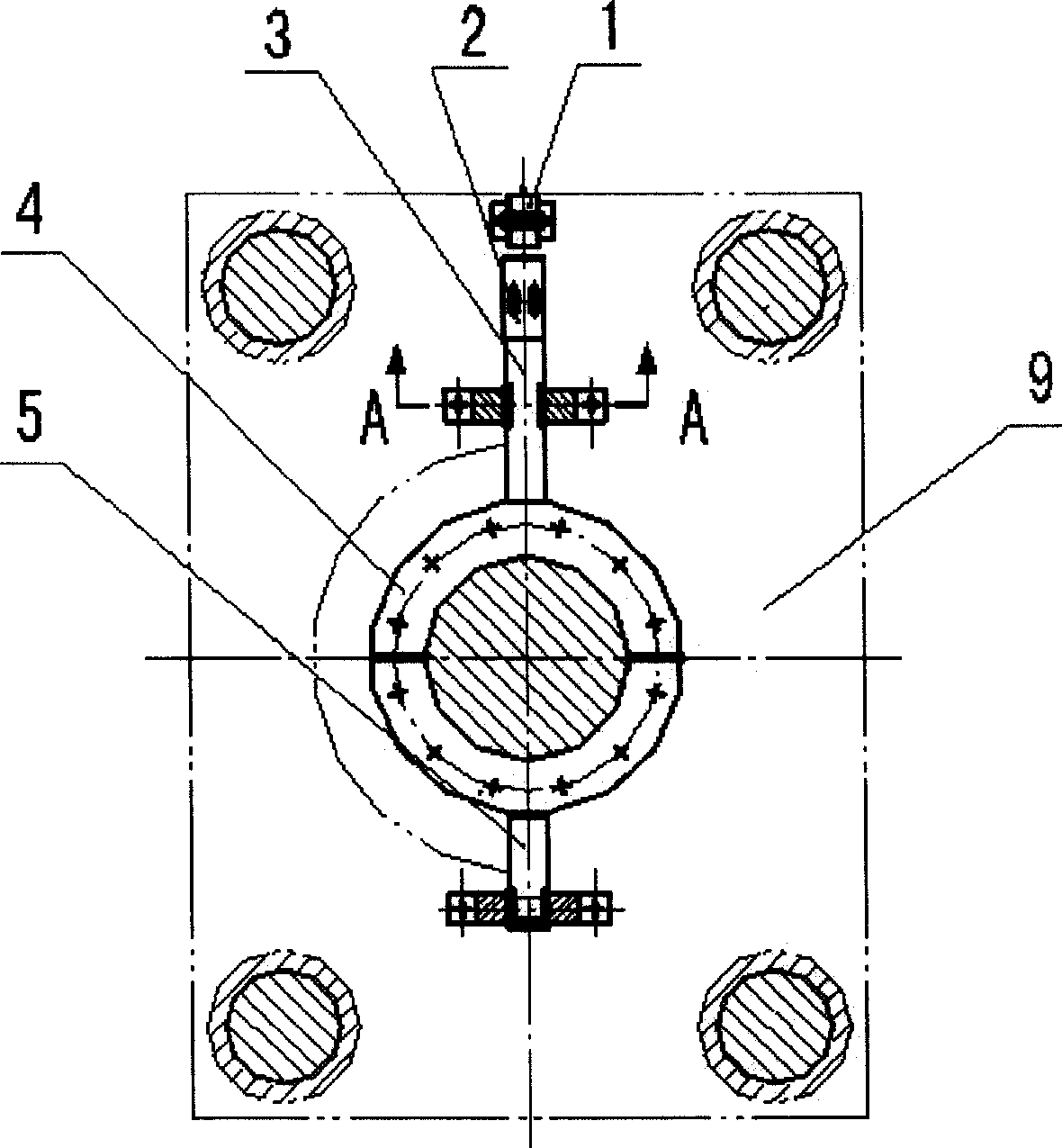
[0017] Embodiment of the present invention: connect according to the diagram. First, connect the proximity switch 1 to the fixing plate 9; secondly, fix the flange 4 on the top surface of the piston rod of the pressure release cylinder with bolts, and weld the torsion arm 3 and the torsion arm 5 on both sides of the flange 4. Connect the induction plate 2 with bolts on the top of 3, and adjust the distance from the proximity switch 1 by using the oblong hole on the induction plate 2; 7 and the connecting plate 8 are connected with countersunk head screws, and the inlays 6 on the torsion arm 3 and the torsion arm 5 are placed between the guide rails 7; finally, the connecting plate 8 and the fixing plate 9 can be connected.


PUM


Abstract

The invention discloses a breaking cylinder travel controller of a breaking machine for electrolytic aluminium anode assembling, whose structure is characterized in that an approach switch (1) connects with a fixing plate (9), a flange (4) connects with a top surface of a breaking cylinder piston rod, a torsional arm (3) and a torsional arm (5) connects with the two sides of the flange (4), the torsional arm (3) connects with an induction plate (2), the torsional arm (3) and the torsional arm (5) are disposed in a guide rail (7), the guide rail (7) connects with a connection plate (8), the connection plate (8) connects with a fixed plate (9), wherein the induction plate (2) is provided with a long round hole, and the torsional arm (3) connects with the induction plate through the long round hole and a bolt, the flange (4) connects with the top surface of the breaking cylinder piston rod by bolts, and inlayed strips (6) are disposed on the torsional arm (3) and the torsional arm (5), the guide rail (7) connects with the connection plate (8) by sunk screws. If the breaking cylinder piston rod wants to deflect when moving, it will be restricted by the guide rail (7).

Description

technical field [0001] The invention relates to a press-off machine for assembling electrolytic aluminum anodes, in particular to a stroke control device of a press-off oil cylinder. Background technique [0002] In the anode assembly process of electrolytic aluminum production, the phosphorus iron ring on the anode guide rod is pressed off the anode guide rod by using a pressing machine. In order to control the stroke of the pressure release cylinder, a stroke control device is installed on the piston rod of the pressure release cylinder. The stroke control device used in the past cannot prevent the accumulated rotational offset of the piston rod during multiple reciprocating movements, which easily leads to poor contact of the stroke switch and loss of control, which affects the normal operation of the press machine. SUMMARY OF THE INVENTION [0003] The purpose of the present invention is to provide a new stroke control device, which can prevent the deflection of the p...

Claims


Application Information

Patent Timeline
Patent Type & Authority Applications(China)
IPC IPC(8): B30B15/16B23P19/02
Inventor 李猛刘兵李梦石王志斌
Owner GUIYANG AL-MG DESIGN & RES INST
Learn More