
Hybrid switched mode/linear power amplifier power supply for use in polar transmitter

A switching mode, power supply technology, used in DC amplifiers with modulator-demodulators, instruments, regulating electrical variables, etc.

Active Publication Date: 2006-12-13
NOKIA TECHNOLOGLES OY
View PDF1 Cites 38 Cited by
  • Summary
  • Abstract
  • Description
  • Claims
  • Application Information

AI Technical Summary

Problems solved by technology

While a switching frequency of 5-10MHz would be technically very challenging (typical commercial DC-DC converters operate at a maximum switching frequency in the range of about 1-2MHz), for example a DC-DC converter with a switching frequency of 100MHz would be Currently impractical to implement, especially in low-cost, mass-produced devices such as cellular phones and personal communication terminals

Method used


Image

  • Hybrid switched mode/linear power amplifier power supply for use in polar transmitter
  • Hybrid switched mode/linear power amplifier power supply for use in polar transmitter
  • Hybrid switched mode/linear power amplifier power supply for use in polar transmitter

Examples


Embodiment Construction

[0047] refer to Figure 5 , the present invention provides a hybrid voltage regulator or power supply 30 that combines a switching section 32 that preferably handles most of the power with high efficiency but low bandwidth and a smaller portion of the required power that is best handled with low efficiency but high bandwidth The linear part of 34. The resulting power supply has the required bandwidth and efficiency slightly lower than that of a pure switching power supply but still much higher than that of a pure linear regulator. The resulting hybrid power supply 30 provides an improved output voltage quality since the linear section 34 can be used to compensate for the output voltage ripple typically associated with a pure switching power supply. This is an important advantage since excess output voltage ripple can adversely affect the output spectrum of the PA 6.

[0048] It is to be noted that in principle the amount of power (x) handled by the switching section 32 is gr...


PUM


Abstract

In one aspect this invention provides a DC-DC converter that has a switch mode part for coupling between a DC source and a load, the switch mode part providing x amount of output power; and that further has a linear mode part coupled in parallel with the switch mode part between the DC source and the load, the linear mode part providing y amount of output power, where x is preferably greater than y, and the ratio of x to y may be optimized for particular application constraints. In a further aspect there is a radio frequency (RF) transmitter (TX) for coupling to an antenna, where the TX has a polar architecture having an amplitude modulation (AM) path coupled to a power supply of a power amplifier (PA) and a phase modulation (PM) path coupled to an input of the PA.

Description

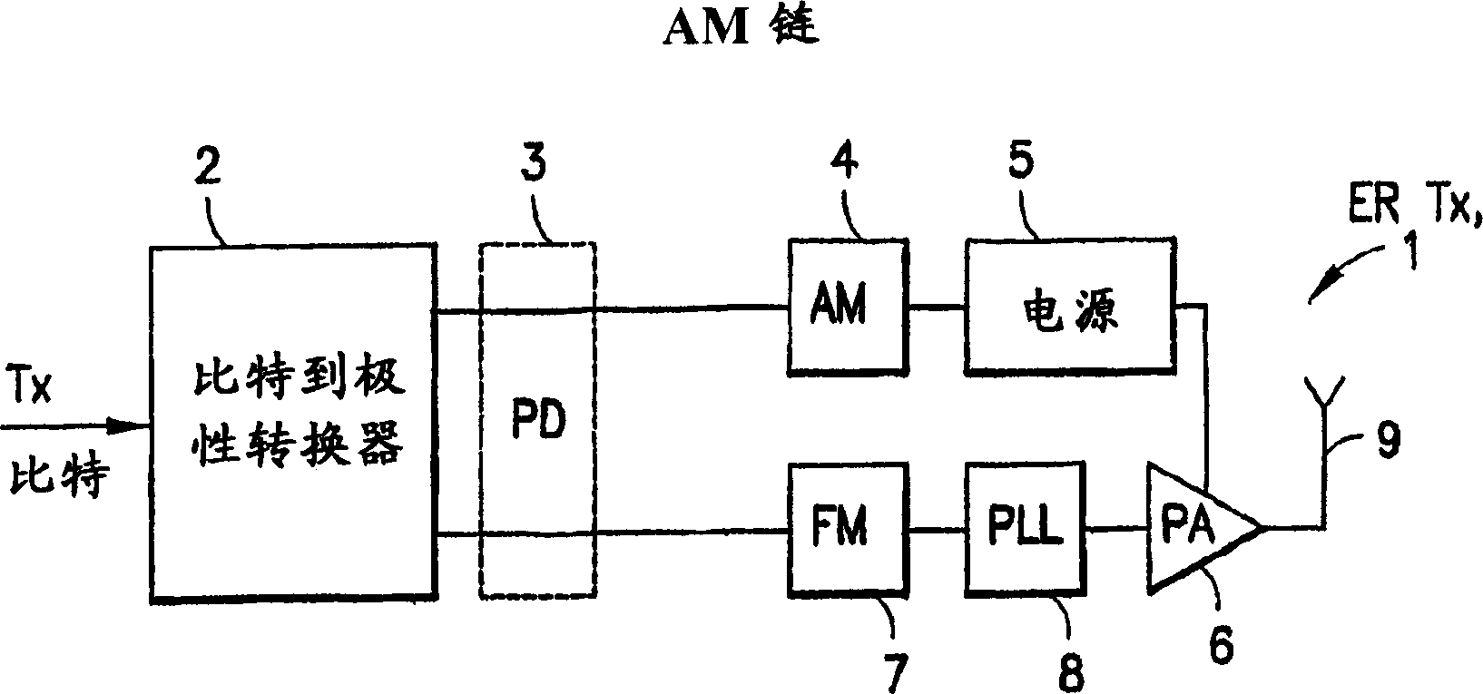
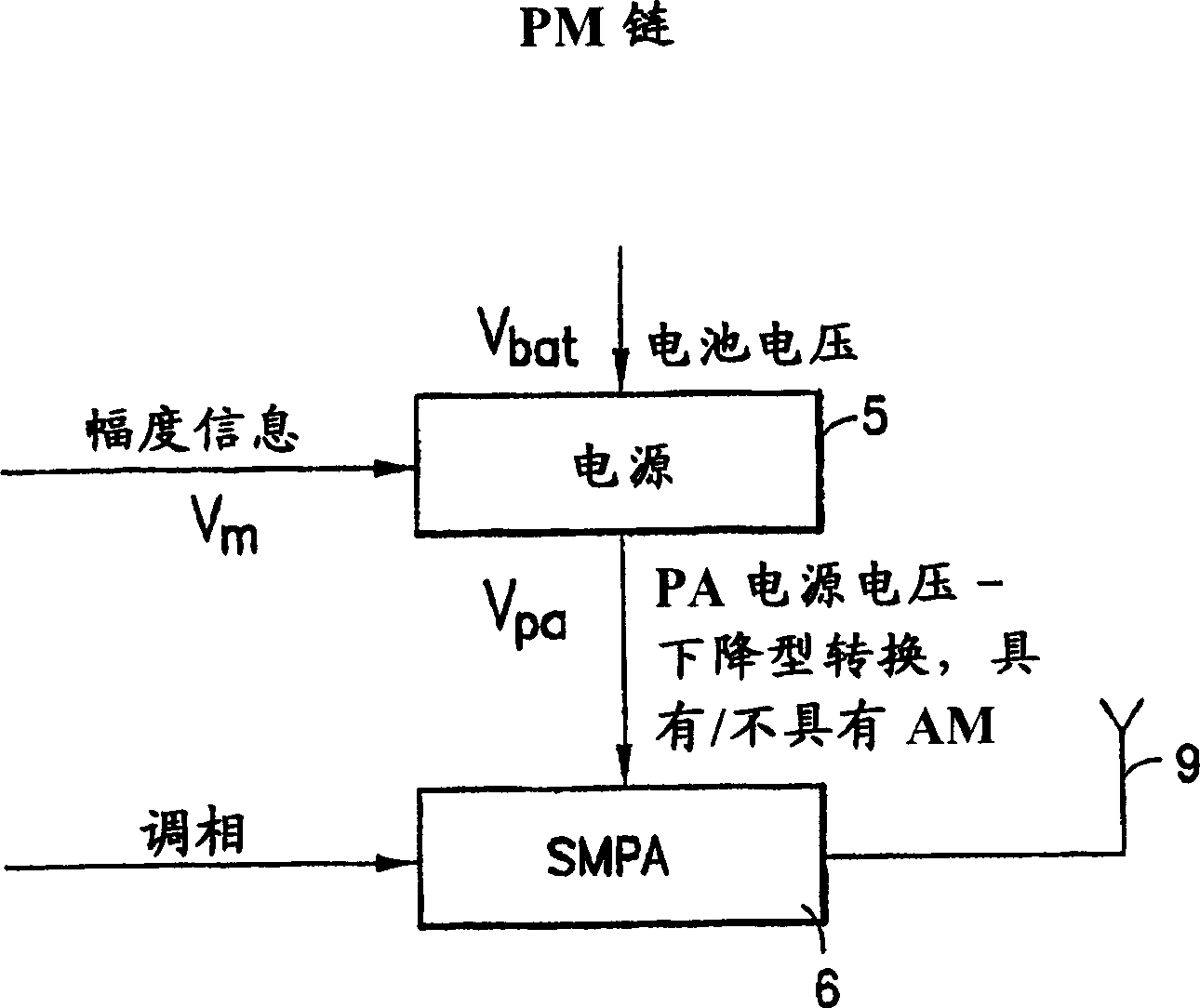
technical field [0001] The present invention relates generally to DC-DC converter power supplies, and more particularly to switched-mode power supplies (SMPS) suitable for use in radio frequency (RF) transmitters, such as those used in cellular mobile stations implementing envelope recovery ( ER) RF transmitters RF transmitters, also known as polar transmitters, in which the sign is represented using phase and magnitude components, rather than complex in-phase / quadrature-phase (I / Q) components. Background technique [0002] Figure 1A is a simplified block diagram showing the structure of the ER transmitter (TX) 1 including the amplitude modulation (AM) chain and phase modulation (PM) chain. The bits to be transmitted are input to a bit-to-polarity converter 2, which outputs an amplitude signal via a propagation delay (PD) 3 to an amplitude modulator (AM) 4 . AM4 (after digital-to-analog conversion) provides a signal for controlling the output level of a TX power amplifier ...

Claims


Application Information

Patent Timeline
IPC IPC(8): G05F1/40H03F3/38
Inventor V·G·格里戈尔
Owner NOKIA TECHNOLOGLES OY
Learn More