Laser image display
一种图像显示装置、激光的技术,应用在放映装置、图像通信、利用投影装置图像重现器等方向,能够解决未进行过讨论等问题
- Summary
- Abstract
- Description
- Claims
- Application Information
AI Technical Summary
Problems solved by technology
Method used
Image

Examples
Embodiment 1
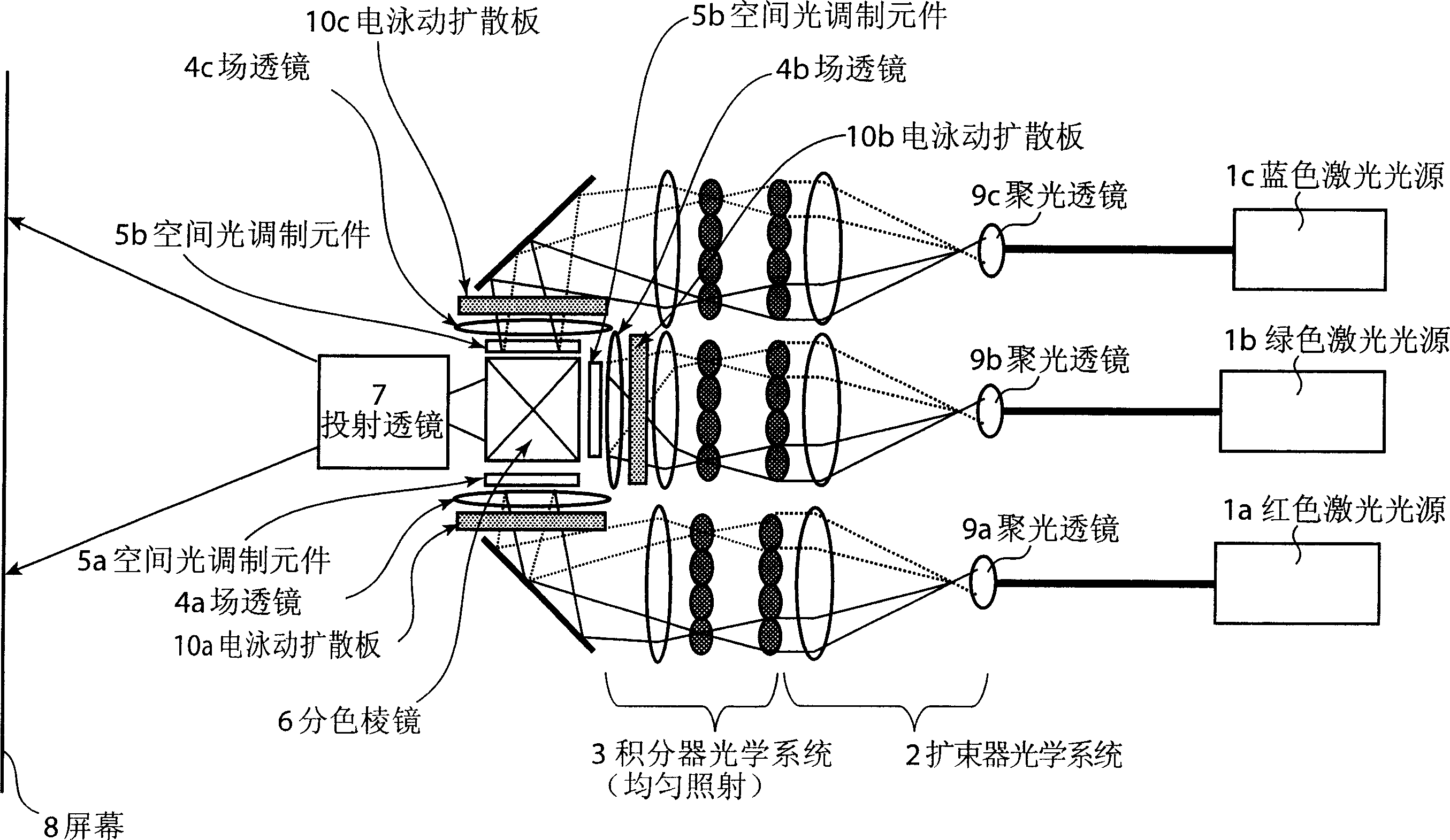
[0023] figure 1 The schematic structure of the laser image display apparatus of this invention is shown. Light emitted from the red laser light source 1a, the green laser light source 1b, and the blue laser light source 1c are condensed by condenser lenses 9a, 9b, and 9c, respectively. The condensed light passes through the beam expander optical system 2 and the integrator optical system (illumination optical system) 3, and after being shaped into a beam with uniform light intensity distribution, it is irradiated on the electrophoretic diffuser plate (light diffusion unit) (electrophoretic diffuser unit) respectively. ) 10a, 10b, 10c. The light incident on the electrophoretic diffusion plates 10a, 10b, and 10c is scattered by the light scattering objects enclosed therein. As a result, the traveling direction of light passing through the electrophoretic diffusion plates 10a, 10b, and 10c is diffused.
[0024] The laser light diffused by the electrophoretic diffusion plates ...
Embodiment 2
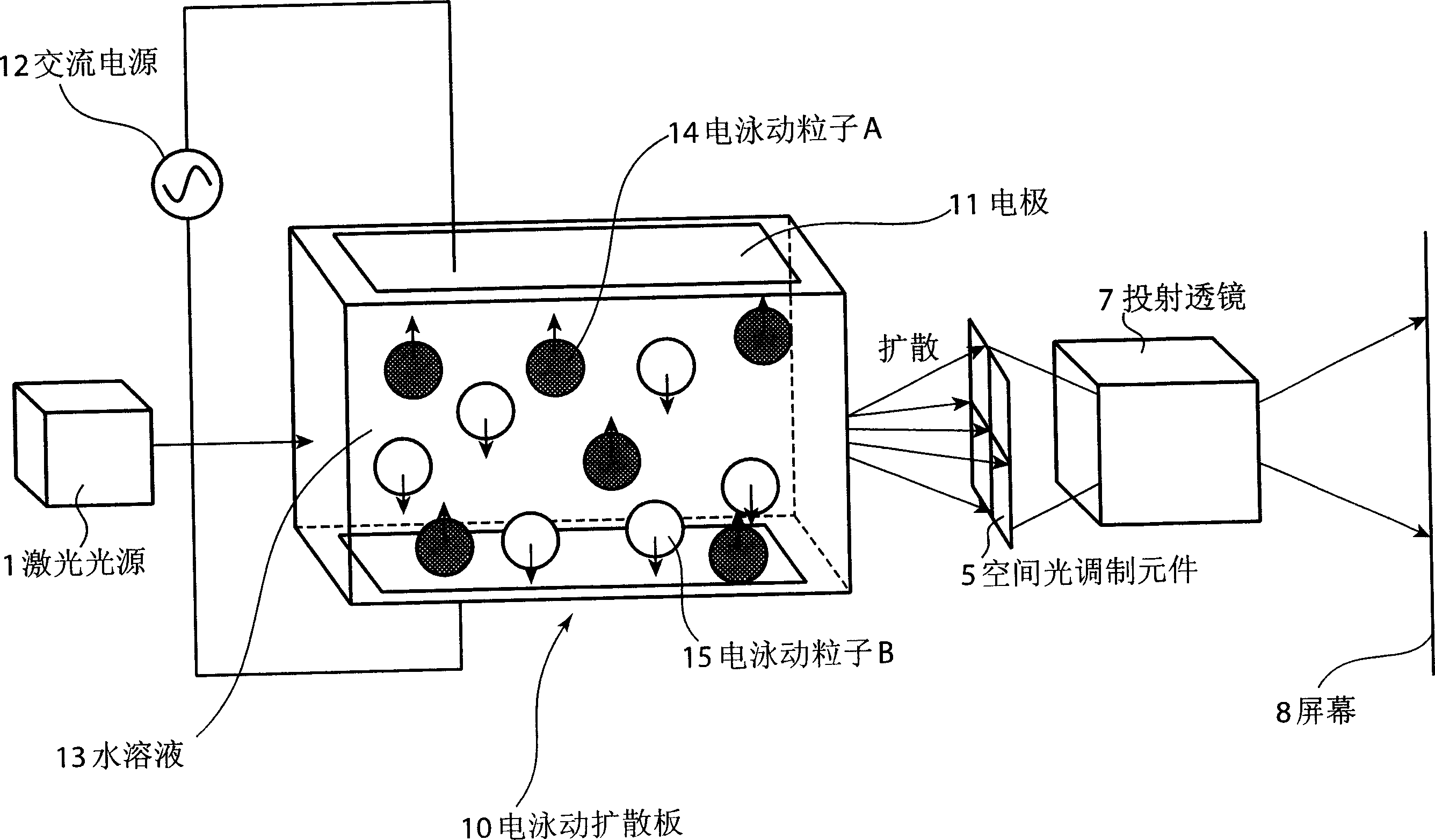
[0052] In addition, another structure of the laser image display device of the present invention, such as Figure 4 As shown, the speckle noise is reduced and removed by integrating the electrophoretic diffusion plate 10 sealed with light scattering objects and the spatial light modulation element 5 . Here, optical systems such as the integrator optical system 3 are omitted for simplicity. In this structure, after the light beam emitted from the light source passes through the beam expander optical system and the integrator optical system, the light beam can be irradiated in a uniform illuminating light state on the optical system integrated with the electrophoretic moving scattering plate 10 and the spatial light modulation element 5. on the system. Alternatively, it can be as Figure 5 The shown spatial light modulation element is a reflective spatial light modulation element structure. Here, LCOS (Liquid Crystal On Silicon), which is representative of the reflective liqu...
Embodiment 3
[0054] In addition, another structure of the laser image display device of the present invention, such as Figure 6 As shown, a diffuser plate enclosing a light-scattering object and a liquid crystal used in a two-dimensional spatial light modulator for projecting images are enclosed in the same liquid. For example, by making the particles flow under the action of heat, it functions as a diffusion plate, and on the other hand, by controlling the liquid crystal ( Figure 6 Reflective liquid crystal is used in it), so that it can function as a two-dimensional light modulation element.
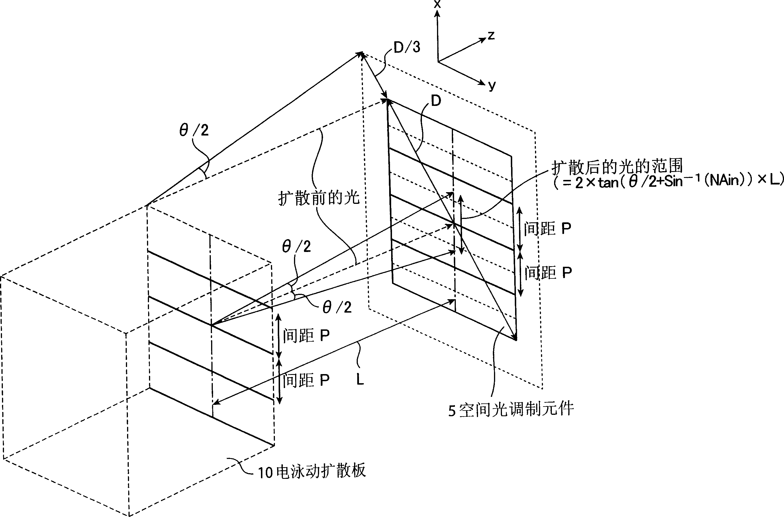
[0055] Here too, as in Example 1, in order to minimize light loss and brightness unevenness, it is necessary to arrange the distance between the diffusion plate and the light modulation element at an optimum position. Therefore, it is necessary to separate the positions of the diffusion function and the light modulation function, and the particles and liquid crystals enclosed in the same liquid ...
PUM
 Abstract
Description
Claims
Application Information
 - R&D
- Intellectual Property
- Life Sciences
- Materials
- Tech Scout
- Unparalleled Data Quality
- Higher Quality Content
- 60% Fewer Hallucinations
Browse by: Latest US Patents, China's latest patents, Technical Efficacy Thesaurus, Application Domain, Technology Topic, Popular Technical Reports.
© 2025 PatSnap. All rights reserved.Legal|Privacy policy|Modern Slavery Act Transparency Statement|Sitemap|About US| Contact US: help@patsnap.com