
Stylus antenna and portable electronic device thereof

An electronic device, portable technology, applied in antenna support/mounting device, antenna equipment with additional functions, mechanical mode conversion, etc., can solve the problem that the planar antenna cannot meet the bandwidth requirements of receiving digital TV signals, etc.

Inactive Publication Date: 2006-12-13
HTC CORP
View PDF0 Cites 2 Cited by
  • Summary
  • Abstract
  • Description
  • Claims
  • Application Information

AI Technical Summary

Problems solved by technology

The bandwidth of traditional planar antennas obviously cannot meet the bandwidth requirements of receiving digital TV signals

Method used


Image

  • Stylus antenna and portable electronic device thereof
  • Stylus antenna and portable electronic device thereof
  • Stylus antenna and portable electronic device thereof

Examples


Embodiment Construction

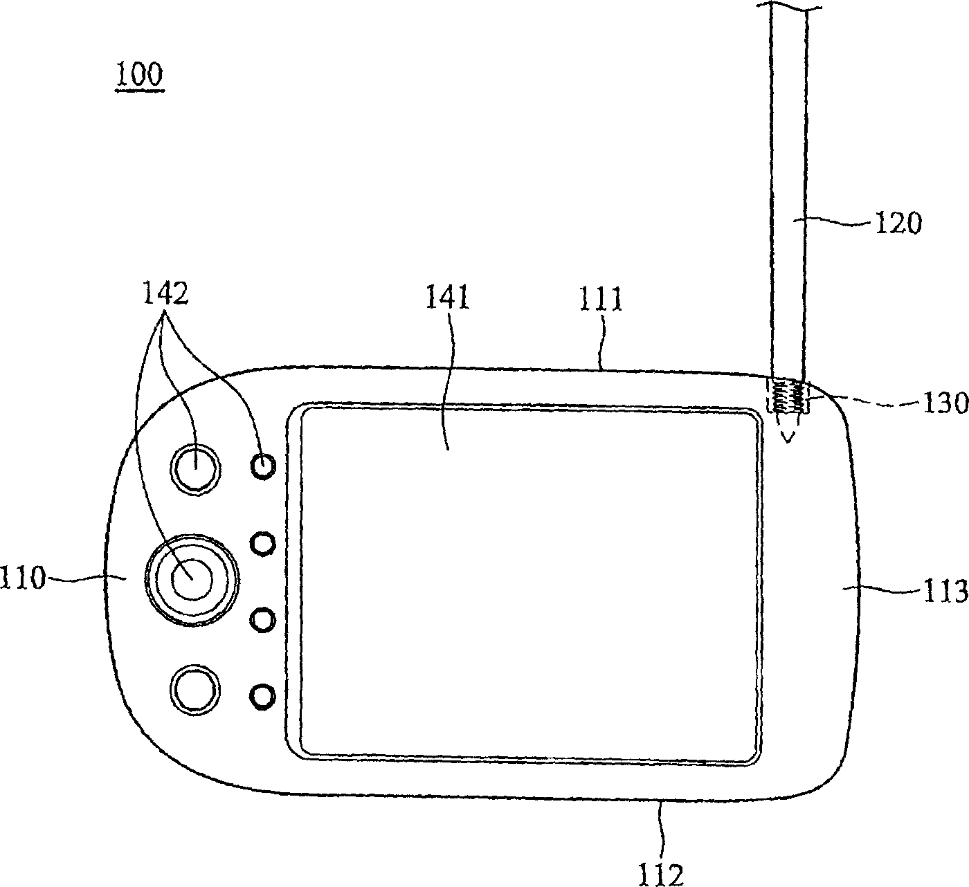
[0035] refer to Figure 2a , which shows a portable electronic device 100 applying the stylus antenna of the present invention, including a casing 110 , a screen 141 , a control interface 142 and an antenna 120 . The casing 110 has a first side surface 111 , a second side surface 112 and a main plane 113 . The screen 141 and the control interface 142 are both disposed on the main plane 113 of the casing 110 . The screen 141 is a touch screen. The antenna 120 passes through the first side surface 111 of the casing 110 and connects to a connection port (screw seat) 130 inside the casing 110 . The antenna 120 can receive a wireless signal, and transmit the wireless signal to the portable electronic device 100 through the connection port 130 .

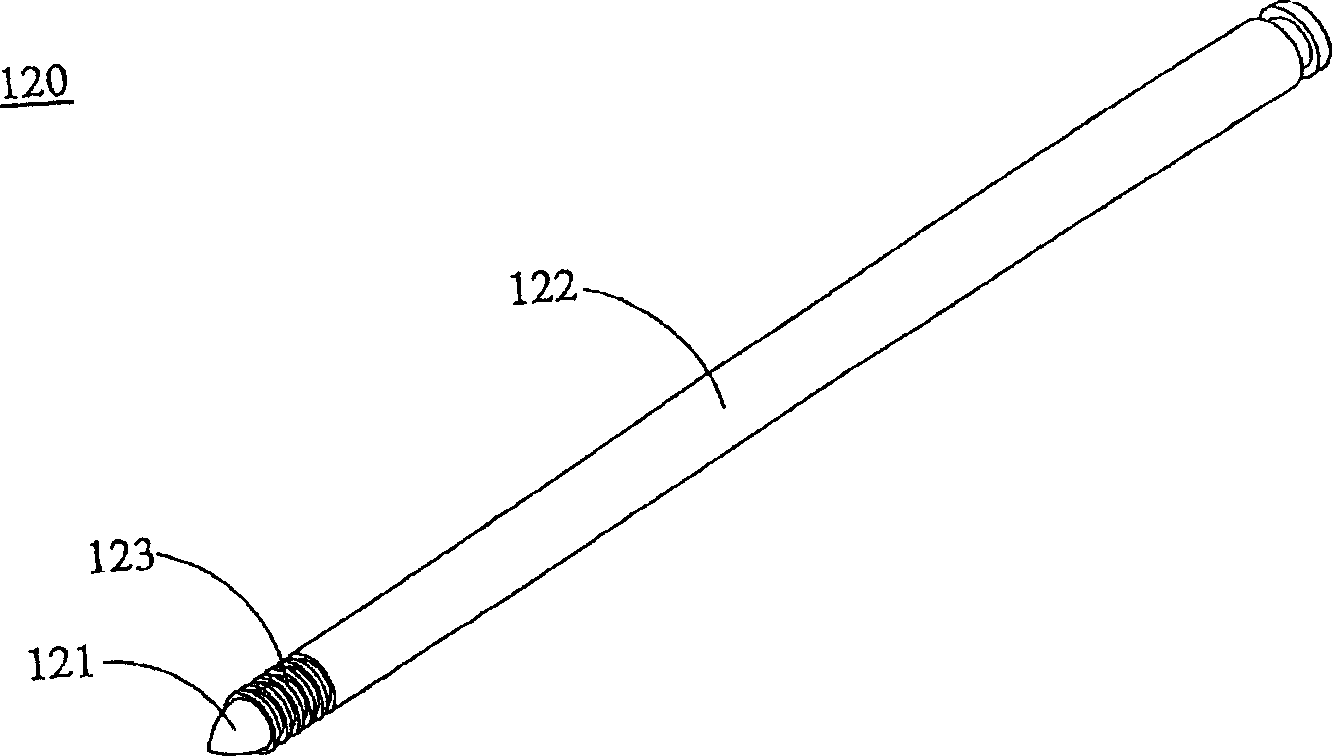
[0036] refer to Figure 2b , the antenna 120 is a stylus and includes a first section 121 and a second section 122 . The first section 121 is made of plastic material and has a conical shape. The plastic material can be used for touch...


PUM


Abstract

The invention discloses a stylus antenna, which contains a stylus pen with metal ingredient and plastic material for pen end, screw seat and circuit base, wherein the metal besides plastic material possesses screw, which fixes the stylus pen; the stylus pen itself is antenna bulk, which makes stylus pen extract out of containing groove; the screw seat locks the stylus pen on the screw seat; the circuit base welds the surface of screw seat on the circuit base.

Description

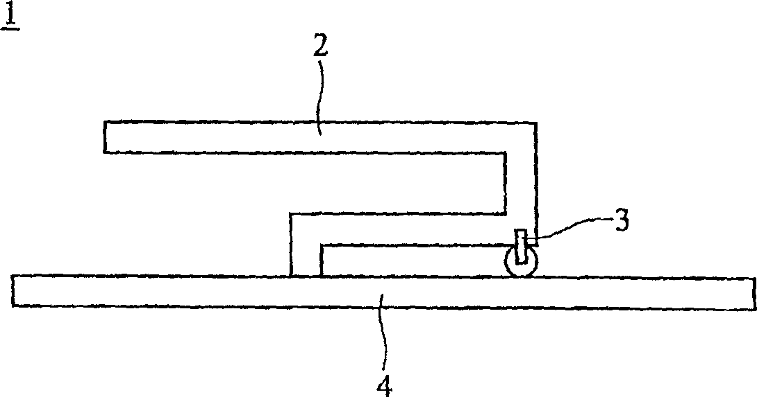
Technical field: [0001] The present invention relates to a portable electronic device, in particular to a portable electronic device using a stylus as an antenna. Background technique: [0002] At present, general portable electronic devices use planar antennas to transmit signals, such as figure 1 What is shown is a simple planar antenna 1 including a signal receiving component 2 , a signal line 3 and a grounding component 4 . The signal receiving component 2 is connected to the grounding component 4 . The signal line 3 is electrically connected to the signal receiving component 2 . Due to limitations in design and principle, the bandwidth of the traditional planar antenna 1 is only between 40-50 MHz. [0003] However, with the development of digital video technology, the antenna in the portable electronic device needs to be able to receive video signals of different frequencies to watch many different TV stations, that is, a huge video signal receiving bandwidth is requ...

Claims


Application Information

Patent Timeline
IPC IPC(8): H01Q1/44H01Q1/22H01Q1/24G06K11/06G06F3/033G06F3/0354
Inventor 郭彦良陈允达
Owner HTC CORP
Learn More