Granular measuring device and in-situ measuring method thereof
A measuring device and in-situ measurement technology, applied in the direction of analyzing materials, instruments, etc., to achieve the effect of expanding the applicable surface
- Summary
- Abstract
- Description
- Claims
- Application Information
AI Technical Summary
Problems solved by technology
Method used
Image


Examples
Embodiment 1
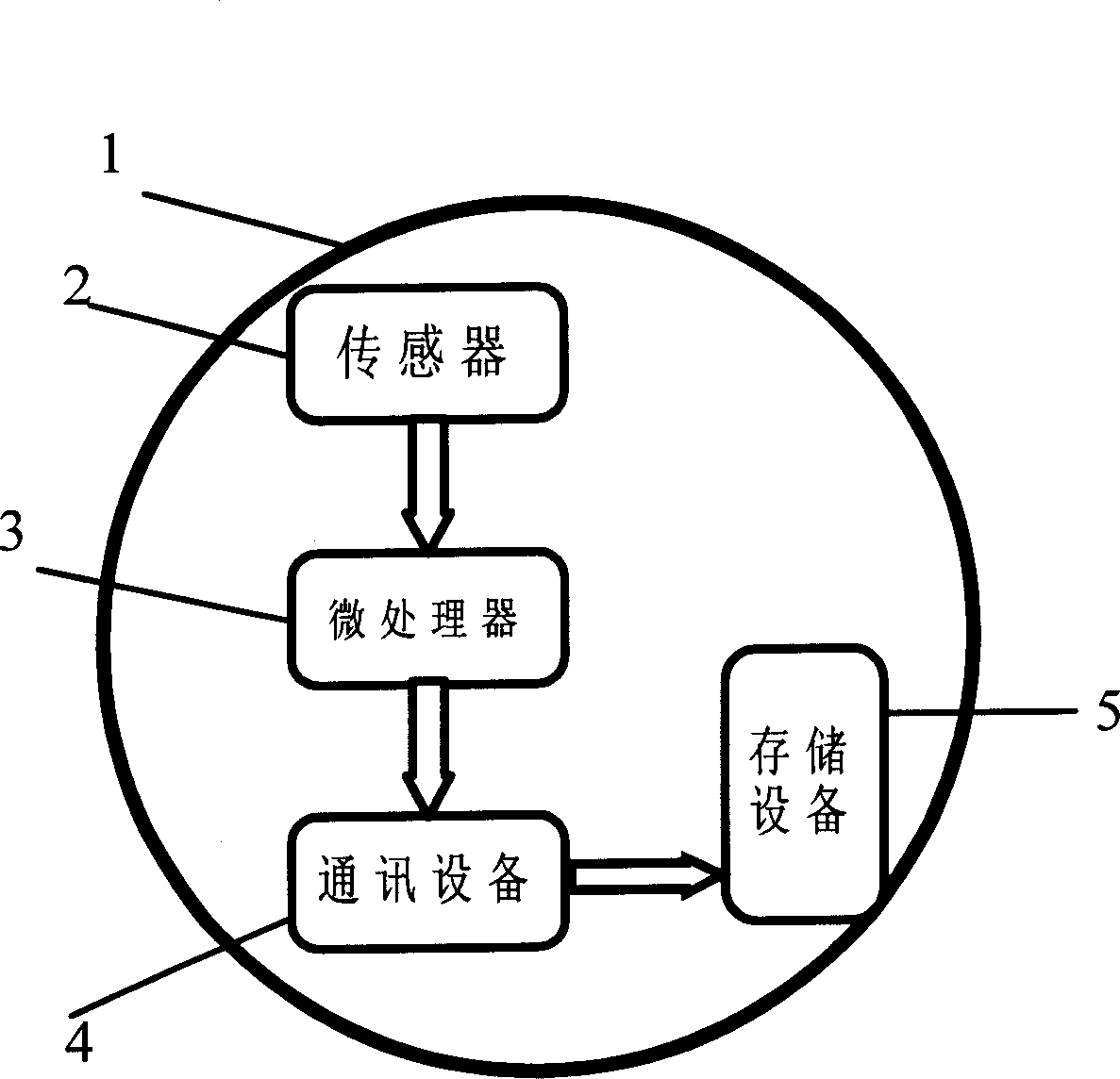
[0027] Embodiment 1: A granular measuring device based on an external storage device of an acceleration sensor.
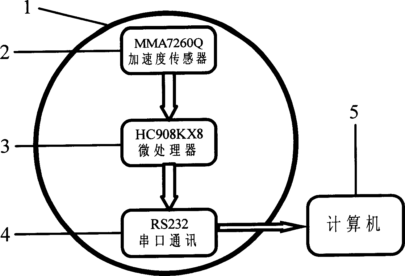
[0028] Taking the granular measurement device based on the acceleration sensor as an example, the sensor 2 adopts MMA7260Q, and the storage device 5 adopts an external computer, such as figure 2 shown. The analog output signal of the acceleration sensor is converted into a digital signal by the microprocessor 3 (chip model: HC908KX8), and the digital signal is connected to the computer through the communication device 4, that is, through the RS232 serial port. Wherein the acceleration sensor MMA7260Q, the microprocessor HC908KX8, and the RS232 serial port are integrated on a circuit board, and these devices and the system power supply are packaged together in a granular shell 1 with a diameter of 60mm made of stainless steel. In this way, a granular measuring device based on an external storage device of an acceleration sensor is formed.
Embodiment 2
[0029] Embodiment 2: Granular measuring device based on the built-in storage device of the acceleration sensor
[0030] Taking the granular measurement device based on the acceleration sensor as an example, the sensor 2 adopts MMA7260Q, and the storage device 5 adopts an external computer, such as image 3 shown. The analog output signal of the acceleration sensor is converted into a digital signal by the microprocessor 3 (chip model: HC908KX8), and the digital signal is connected to the USB flash memory through the communication device 4 through the USB conversion interface. The acceleration sensor MMA7260Q, the microprocessor HC908KX8, the RS232 serial port, the USB conversion interface, and the USB flash memory are integrated on a circuit board, and these devices and the system power supply are packaged together in a plexiglass granular shell 1 with a diameter of 65 mm. In this way, a granular measurement device built into a storage device based on an acceleration sensor i...
Embodiment 3
[0031] Example 3: In-situ measurement of particle motion based on granular measuring device
[0032] The particle motion measurement experiment was carried out using a particle measurement device based on an acceleration sensor. The granular measuring device is placed in the air for free-fall movement, and the internal acceleration sensor senses the instantaneous acceleration of the device during the free-fall process, and records the instantaneous acceleration into the storage device through the microprocessor and communication equipment. Then read the acceleration of the free fall of the device from the storage device, and then obtain the trajectory of the free fall of the object through the quadratic integration of time, see the result Figure 4 . Among them, "line" represents the curve whose theoretical value is calculated by free fall, and "point" represents the trajectory value obtained by quadratic integration of the acceleration of the particle itself. It can be seen...
PUM
| Property | Measurement | Unit |
|---|---|---|
| Equivalent diameter | aaaaa | aaaaa |
| Diameter | aaaaa | aaaaa |
Abstract
Description
Claims
Application Information
 - R&D
- Intellectual Property
- Life Sciences
- Materials
- Tech Scout
- Unparalleled Data Quality
- Higher Quality Content
- 60% Fewer Hallucinations
Browse by: Latest US Patents, China's latest patents, Technical Efficacy Thesaurus, Application Domain, Technology Topic, Popular Technical Reports.
© 2025 PatSnap. All rights reserved.Legal|Privacy policy|Modern Slavery Act Transparency Statement|Sitemap|About US| Contact US: help@patsnap.com