Method for controlling charging and discharging currents of adjuster for superconducting magnet

A current regulator, charging and discharging current technology, applied in the direction of conversion equipment with intermediate conversion to AC, can solve the problems of easily damaged switching tube, large switching loss, etc., to reduce switching loss, improve stability, and improve system performance Effect

Inactive Publication Date: 2006-12-06
INST OF ELECTRICAL ENG CHINESE ACAD OF SCI
View PDF1 Cites 8 Cited by
  • Summary
  • Abstract
  • Description
  • Claims
  • Application Information

AI Technical Summary

Problems solved by technology

Due to the large current passing through the superconducting magnet, it can be seen from the above switching action that the switching tube of the current source converter always needs to be turned on and off to realize

Method used


Image

  • Method for controlling charging and discharging currents of adjuster for superconducting magnet
  • Method for controlling charging and discharging currents of adjuster for superconducting magnet
  • Method for controlling charging and discharging currents of adjuster for superconducting magnet

Examples


Example Embodiment

[0021] The present invention will be further described below in conjunction with the drawings and specific embodiments:

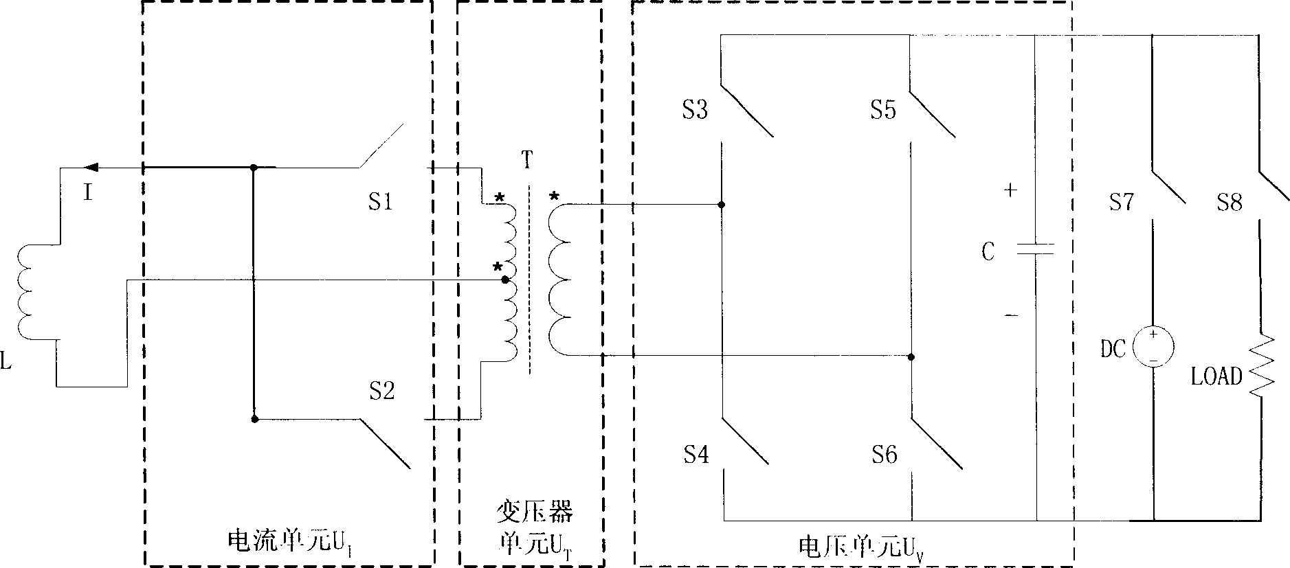
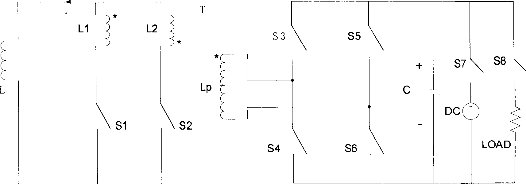
[0022] The main circuit diagram of the patent 03137460.3 is as follows figure 1 As shown, figure 2 It is the main circuit schematic diagram of patent 03137460.3.

[0023] figure 2 It is the main circuit schematic diagram of patent 03137460.3. Such as figure 2 As shown, the patent 03137460.3 consists of the voltage unit U V , Transformer unit U T , And the current unit U I It consists of three parts. Transformer unit U T Is the current unit U I Transformer T with a tap on the connected side. Voltage unit U VFor the DC side, the capacitor C is connected in parallel with the two bridge arms of the voltage source converter composed of switches S3 and S4, S5 and S6 in series. The midpoint of the two bridge arms is the voltage source converter. The AC output is connected to the primary side of the transformer T. Current unit U I It is a current source converter,...


PUM


Abstract

Characters of the method for controlling current regulator of charging and discharging superconducting magnet are as following: through relative phase shift between leading and lag bridge arms, unit of voltage (UV) in full bridge phase shift control mode adjusts charging and discharging power; through UV, auxiliary electric potential is supplied for unit of current; in time of phase change, switch tubes on two branches of converter in current source gives trigger signal to switch tube to be turned on first, and then, to switch tube of controlling converter of UV; thus, commutation voltage is generated at primary side of transformer, and converted into secondary side; the related current is opposite to current of switch tube to be turned off so as to turn off the switch tube when current is reduced to zero; and the related current is same to current of switch tube to be turned on so as to increase current. Features are: reducing loss of switch tube, and increasing stability of system.

Description

technical field [0001] The invention relates to a control method for a superconducting magnet charging and discharging current regulator, in particular to an auxiliary potential phase-shifting control method for the current regulator. Background technique [0002] The characteristics of zero resistance and high current-carrying capacity under a strong magnetic field make superconducting magnets widely used, especially large magnets used to generate strong magnetic fields in high-energy physics experiments. Superconducting magnets have almost replaced all conventional magnets with large volume and high power consumption; at the same time, with the development of superconducting power technology, especially micro-superconducting energy storage, it has been commercialized abroad and is widely used to improve power quality and increase Power system stability, etc., these have made superconducting magnets have been used in unprecedented applications. [0003] The general operati...

Claims


Application Information

Patent Timeline
IPC IPC(8): H02M3/28
Inventor 赵彩宏李顺郭文勇肖立业林良真余运佳
Owner INST OF ELECTRICAL ENG CHINESE ACAD OF SCI
Why Eureka
Try Eureka