
Mixing excitation permanent magnetic synchro generator

A permanent magnet synchronous and hybrid excitation technology, which is applied to synchronous motors with stationary armatures and rotating magnets, magnetic circuit rotating parts, magnetic circuit shape/style/structure, etc., can solve the problem of large excitation current and motor electric excitation. Increased magnetic circuit reluctance, low motor efficiency, etc., to achieve the effect of small electric excitation loss, stable voltage output, and no risk of demagnetization

Inactive Publication Date: 2006-11-29
SHENYANG POLYTECHNIC UNIV
View PDF0 Cites 19 Cited by
  • Summary
  • Abstract
  • Description
  • Claims
  • Application Information

AI Technical Summary

Problems solved by technology

However, both sides of the horizontal magnetic pole of the electric excitation part of the generator are air gaps with small lengths, and the processing and assembly precision requirements are very high, which obviously increases the assembly man-hours and manufacturing costs.
At the same time, the horizontal magnetic pole and the vertical magnetic pole provide a path for the electric excitation flux, which requires a large magnetic conduction area, which reduces the power density of the motor
Due to the existence of two additional air gaps, the reluctance of the electric excitation magnetic circuit of the motor increases significantly, resulting in a large excitation current and low efficiency of the motor
[0005] Algerian scholar Yacine Amara and others proposed a shunt-excited hybrid excitation motor structure. The stator structure and rotor structure of the motor are too complicated, the manufacturing and assembly costs are significantly increased, and the power density of the motor is not high, the torque fluctuation is large, and the noise is large. , serious flux leakage

Method used


Image

  • Mixing excitation permanent magnetic synchro generator
  • Mixing excitation permanent magnetic synchro generator

Examples


Embodiment

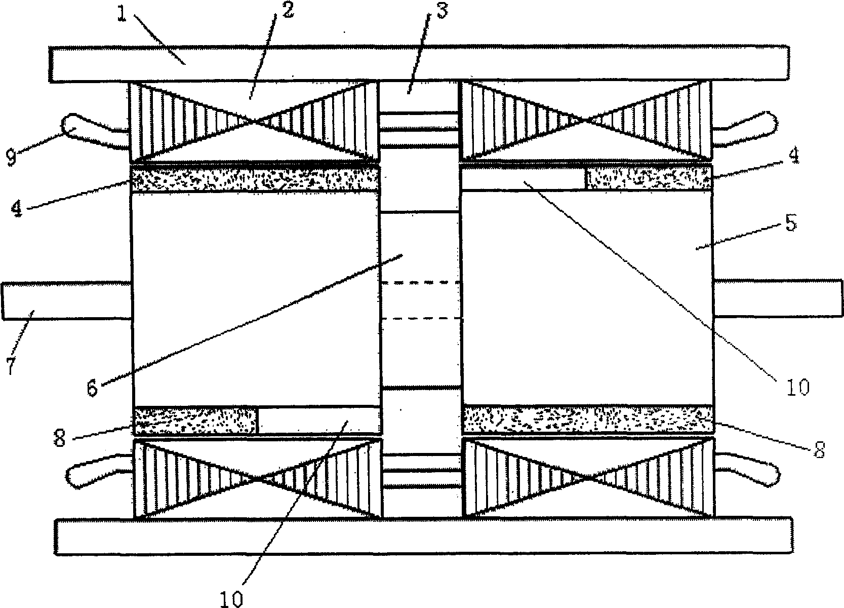
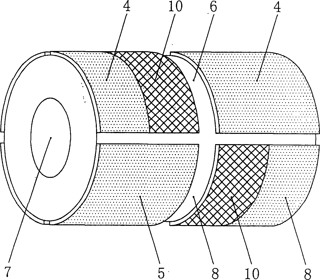
[0014] Example: such as figure 1 As shown, the structure of the present invention includes a housing 1, a stator core 2, a DC field winding 3, a rotor core 5, a rotating shaft 7, a stator armature winding 9 and a permanent magnet, and the stator core 2 is fixed on the housing along the axial direction of the housing , the rotor core 5 is placed on the rotating shaft 7 inside the stator core 2, supported by bearings and machine bases, the stator core 2 and the rotor core 5 are divided into two sections along the axial direction, and the segmented stator cores 2 are respectively connected to the housing 1 , and is connected mechanically and electromagnetically through the housing 1, a ring-shaped DC field winding 3 is placed between the segmented stator cores 2, and the stator armature winding 9 is a three-phase symmetrical winding, which is respectively placed in each segment of the stator core 2, a solid magnetic sleeve 6 is placed on the rotating shaft between the segmented r...


PUM


Abstract

A mixed excitation permanent synchronous generator includes a shell, a stator core, a DC excitation winding, a rotor core, a shaft, a stator armature winding and a magnet, in which, the stator and the rotor cores are divided into two sections along the shaft, the segmented stator cores are connected with the shell and a ring DC excitation winding is set between them, the stator armature winding is a three-phase symmetric winding set in the core slots, a solid magnetic sleeve is set on the shaft between the segmented rotor cores, magnet blocks, magnets and ferromagnetic pole combined blocks are distributed in interleaving along the circles of the cores, the polarities of the adjacent magnets are opposite, the magnets and the ferromagnetic poles are arrayed axially in space along the two sections of the rotor cores, namely, the magnet-ferromagnetic pole-magnet and the polarities of the arrayed magnets in space are the same.

Description

technical field [0001] The invention belongs to the technical field of generators, in particular to a hybrid excitation permanent magnet synchronous generator. technical background [0002] At present, the structures of permanent magnet synchronous generators mainly include series excitation, shunt excitation and combined hybrid excitation motor structures. Since the permanent magnet generator is excited by permanent magnets, once the motor is made into a magnetic field, it cannot be adjusted, and the voltage generated by the generator will change with the load and temperature changes, so it is difficult to ensure that the voltage is constant when the load is working. G. Hennneberger et al. proposed a motor with a series excitation structure. The electric excitation winding of the motor is placed under the permanent magnet of the rotor and does not need to occupy additional space, so the structure is simple and the volume is small. However, the introduction of the rotor exc...

Claims


Application Information

Patent Timeline
IPC IPC(8): H02K1/27H02K21/12
Inventor 唐任远安忠良王惠军
Owner SHENYANG POLYTECHNIC UNIV
Learn More