
Polymer bushing and cable terminal end connector using the same

A technology of polymer and cable end, which is applied in the direction of cable accessories, cable installation, equipment for connecting/terminating cables, etc. It can solve problems such as secondary damage, complex structure, and a large number of parts, so as to reduce auxiliary work and simplify operation steps , the effect of flexible installation

Active Publication Date: 2006-11-15
SWCC SHOWA CABLE SYST CO LTD
View PDF2 Cites 4 Cited by
  • Summary
  • Abstract
  • Description
  • Claims
  • Application Information

AI Technical Summary

Problems solved by technology

[0007] First of all, the first disadvantage is that since the epoxy resin seat for receiving the pressure cone is located inside the porcelain sleeve, the diameter of the porcelain sleeve is correspondingly increased, resulting in a large weight of the porcelain sleeve
[0008] The second disadvantage is that when the outer diameter of the porcelain bushing increases, its projected area increases, resulting in a decrease in the pollution withstand voltage characteristics of the porcelain bushing, so an extended porcelain bushing must be used to maintain the predetermined characteristics of the pollution withstand voltage
[0009] The third disadvantage is that the porcelain bushing is filled with insulating compound, so when the porcelain bushing is broken, the insulating compound may flow out of the porcelain bushing, causing secondary damage
[0010] The fourth disadvantage is that it requires a large number of parts and a complex structure due to the need for components such as epoxy resin mounts, upper cover plates and clamping metal fittings
However, since the connection node between the cable wire 45 of the cable termination 40 and the conductor pull-out rod 42 is located inside the polymer sleeve 41, there is a disadvantage: as in the aforementioned porcelain sleeve, the polymer sleeve 41 The outer diameter will increase, making it heavier
[0017] Secondly, as the operating voltage of the cable termination increases, the polymer sleeve 55 becomes longer, so during installation work, the handling of the polymer sleeve 55 will be changed due to the greater length and higher weight. more difficult

Method used


Image

  • Polymer bushing and cable terminal end connector using the same
  • Polymer bushing and cable terminal end connector using the same
  • Polymer bushing and cable terminal end connector using the same

Examples


Embodiment Construction

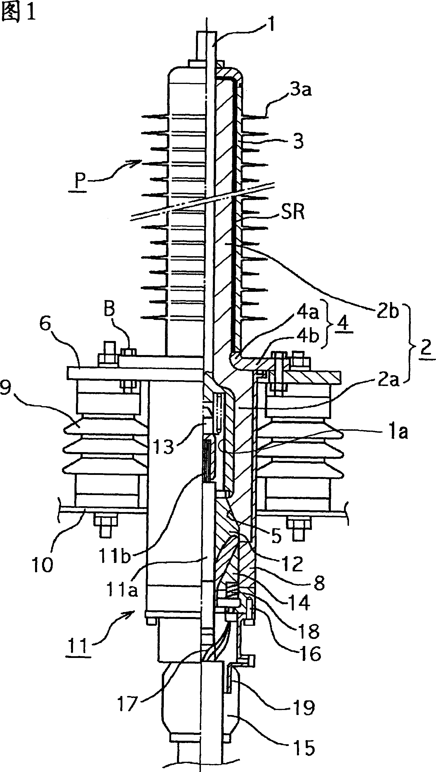
[0047] Now, preferred embodiments of the polymer sleeve of the present invention and a cable termination using the polymer sleeve will be described with reference to the accompanying drawings. Here, FIG. 1 shows a cross-sectional view of an outdoor termination portion of a 22-77 kV class CV cable using the polymer sleeve of the present invention.

[0048] Referring to Fig. 1, the polymer bushing P of the present invention comprises: a conductor pulling rod 1, which is arranged concentrically and has a wire insertion hole 1a at its lower end portion, a hard insulating bushing 2, which surrounds the conductor pulling rod. Arranged around the outer periphery of the rod 1, an electric field stress control layer SR is arranged around the outer periphery of the insulating bush 2, and a polymer coating 3 is arranged around the outer periphery of the electric field stress control layer SR. Here, the insulating bush 2 is formed with a material of high mechanical strength, such as a har...


PUM

PropertyMeasurementUnit
relative permittivityaaaaaaaaaa

Abstract

It is intended to achieve the weight reduction, sliming, and downsizing of bushings, commonality of types of bushings, and simplification of operating steps. A polymer bushing comprises a conductor draw-out bar (1) having a conductor insertion hole (1a) in the lower end, a hard insulation sleeve (2) installed around the outer periphery of the conductor draw-out bar (1), a polymer clad body (3) installed around the outer periphery of the insulation sleeve (2), and an electric field mitigation layer installed on the interface between the insulation sleeve (2) and the polymer clad body (3). The insulation sleeve (2) comprises a large-diameter insulation sleeve (2a) installed around the outer periphery of the lower region of the conductor draw-out bar (1), and a small-diameter insulation sleeve (2b) installed around the outer periphery of a portion of the conductor draw-out bar (1) excluding the front end. An embedment metal part (4) for electric field mitigation purposes is embedded in a portion of connection between the large- and small-diameter insulation sleeves (2a, 2b). Further, installed at the lower end of the large-diameter insulation sleeve (2a) is a cone-shaped receiving port (5) for receiving the stress cone (13) of a cable terminal (11), the receiving port (5) communicating with the conductor insertion hole (1a) in the conductor draw-out bar (1).

Description

technical field [0001] The present invention relates to a polymer sleeve and a cable terminal using the polymer sleeve. More particularly, the present invention relates to a polymer bushing capable of simplifying the structure, reducing the weight, size and length, and facilitating on-site execution, which does not need to be filled with an insulating compound such as insulating oil or insulating gas, and is very suitable for installation In a substation with a low ceiling, or on the cross arm of a high-voltage wire tower. The invention also relates to a cable termination using the polymer sleeve. Background technique [0002] So far, as Figure 8 Cable terminations constructed as shown are known. Referring to the drawings, the prior art cable termination includes a cable termination 20 and a porcelain sleeve 21, which encloses the cable termination 20 and is filled with insulating compound 22, such as insulating oil or insulating gas. [0003] Here, an annular bottom met...

Claims


Application Information

Patent Timeline
Patent Type & Authority Applications(China)
IPC IPC(8): H01B17/00H02G15/064H01B17/26H02G1/14H02G15/068
CPCH02G15/068H01B17/265H01B17/30
Inventor 足立和久濑间信幸
Owner SWCC SHOWA CABLE SYST CO LTD
Learn More