Dual cycloid hydraulic motor
A hydraulic motor and double cycloid technology, applied in the field of hydraulic motors, can solve the problems of small output torque, low mechanical efficiency, and short life, and achieve the effect of large output torque, small loss of mechanical efficiency, and long service life
- Summary
- Abstract
- Description
- Claims
- Application Information
AI Technical Summary
Problems solved by technology
Method used
Image

Examples
Embodiment 1
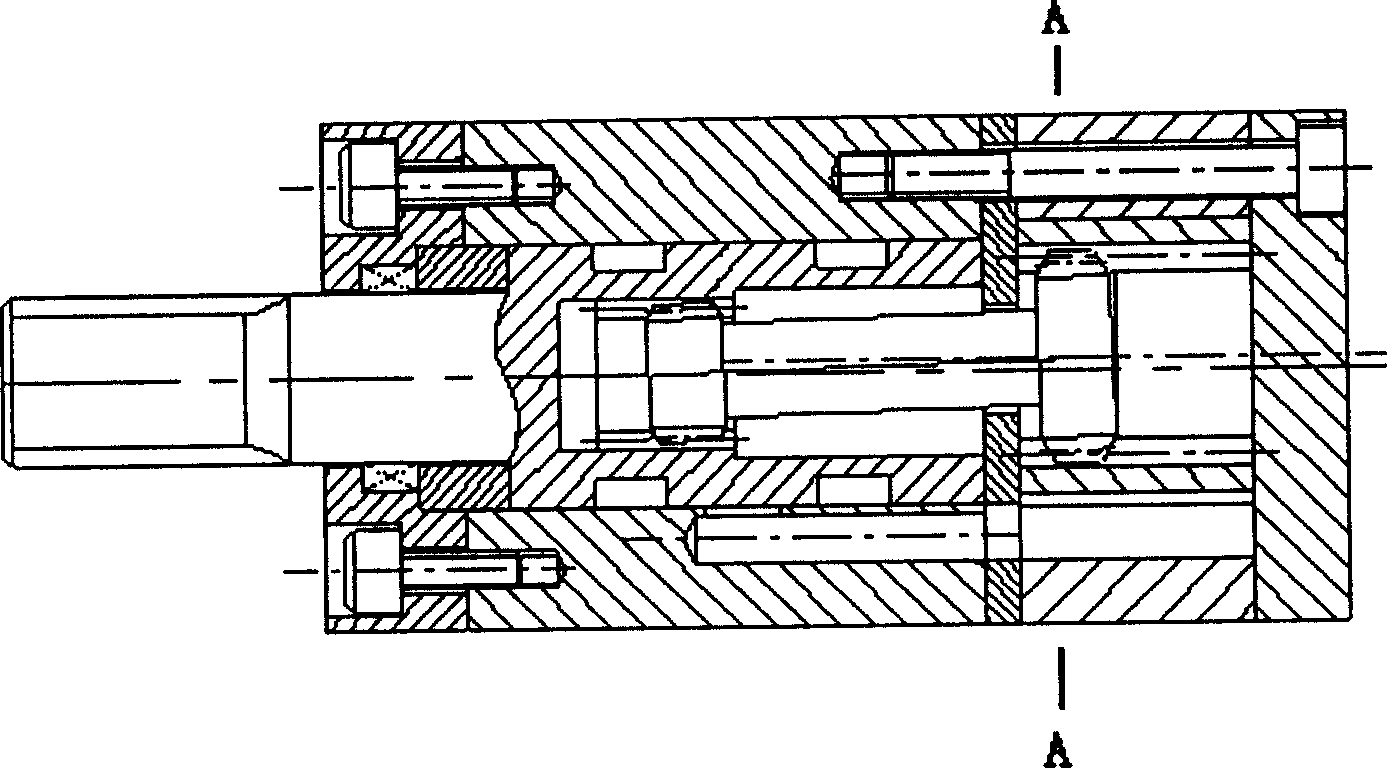
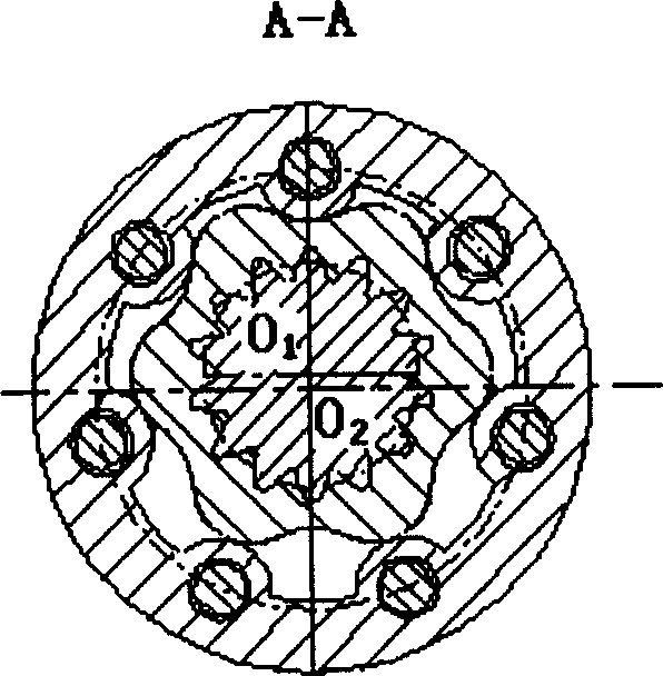
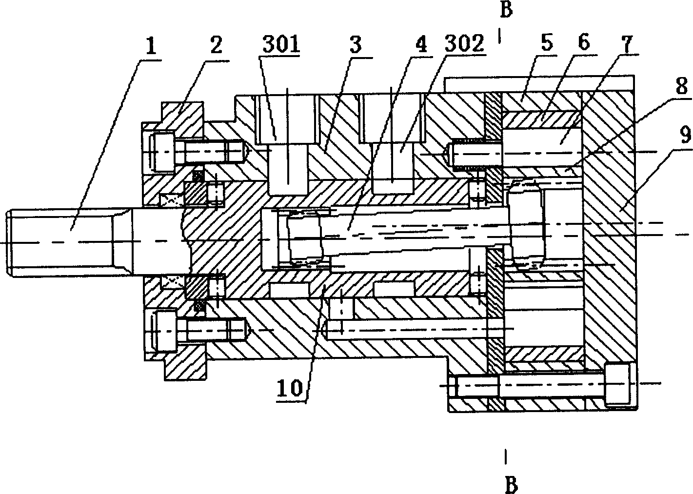
[0030] Such as image 3 , Figure 4Shown, a double cycloid hydraulic motor. The motor is mainly composed of output shaft 1, distribution shaft 10, front end cover 2, machine base 3, spline coupling 4, housing 5, outer rotor 6, pin teeth 7, inner rotor 8, rear end cover 9, etc. components. The inner rotor 8 is a short epicycloid wheel or disc; the pin teeth 7 are eccentric pin teeth, which are positioned by holes and rotate eccentrically. ; The outer rotor 6 is a short hypocycloid ring gear, and the inner rotor 8 is eccentrically arranged relative to the outer rotor 6 . When the inner rotor is a disk, the eccentricity of the pin teeth is equal to the eccentricity of the inner rotor; 1 / 2. The inner rotor 8, the pin teeth 7, and the outer rotor 6 form a plurality of independent closed tooth chambers 11, and these closed tooth chambers 11 are both high pressure chambers and oil discharge chambers. The distribution shaft 10 and the output shaft 1 are an integral shaft structu...
Embodiment 2
[0032] Such as Figure 5 , Figure 6 As shown, a double cycloid hydraulic motor is mainly composed of an output shaft 1, a front end cover 2, a distribution valve 10, a front base 3, a spline coupling 4, a casing 5, and a hypocycloid outer rotor 6 , needle teeth 7, epicycloid inner rotor 8, rear frame 12, rear end cover 9 and other components. The outer rotor 6 is a short-width hypocycloid wheel, the inner rotor 8 is a short-width epicycloid wheel or a disc, and the pin teeth 7 are eccentric pin teeth. The output shaft 1 is fixedly connected with the hypocycloidal outer rotor 6; the pin teeth are positioned by holes and rotate eccentrically, and the centers of the positioning holes of the pin teeth 7 are distributed on the circle centered on the rotation center of the outer rotor; the inner rotor 8 is relative to the outer rotor 6 Eccentric setting. When the inner rotor is a disk, the eccentricity of the pin teeth is equal to the eccentricity of the inner rotor; when the in...
PUM
 Abstract
Description
Claims
Application Information
 - R&D
- Intellectual Property
- Life Sciences
- Materials
- Tech Scout
- Unparalleled Data Quality
- Higher Quality Content
- 60% Fewer Hallucinations
Browse by: Latest US Patents, China's latest patents, Technical Efficacy Thesaurus, Application Domain, Technology Topic, Popular Technical Reports.
© 2025 PatSnap. All rights reserved.Legal|Privacy policy|Modern Slavery Act Transparency Statement|Sitemap|About US| Contact US: help@patsnap.com