Ion beam measuring method and ion implanting apparatus

一种离子注入装置、离子束的技术,应用在测量装置、照射装置、辐射的测量等方向,能够解决降低产率、结构复杂、增加成本等问题,达到减小额外时间、提高产率、简单构造的效果

Inactive Publication Date: 2006-11-08
NISSIN ION EQUIP CO LTD
View PDF3 Cites 8 Cited by
  • Summary
  • Abstract
  • Description
  • Claims
  • Application Information

AI Technical Summary

Problems solved by technology

[0024] However, when measuring the angular offset θ in the y direction of the ion beam 4 y , divergence angle and beam size, when newly providing a Faraday measurement system completely separated from the foreground multipoint Faraday and the background multipoint Faraday provided in the background art for measuring the parallelism of the ion beam 4 etc. in the x direction, (a) increases The measurement system, the structure becomes complicated and significantly increases the cost; (b) in the measurement operation, the operation of exchanging the measurement system in the x direction and the measurement system in the y direction with respect to the beamline of the ion beam 4 is forced, and the exchange Time required for operation becomes additional time and reduces productivity

Method used


Image

  • Ion beam measuring method and ion implanting apparatus
  • Ion beam measuring method and ion implanting apparatus
  • Ion beam measuring method and ion implanting apparatus

Examples


Embodiment Construction

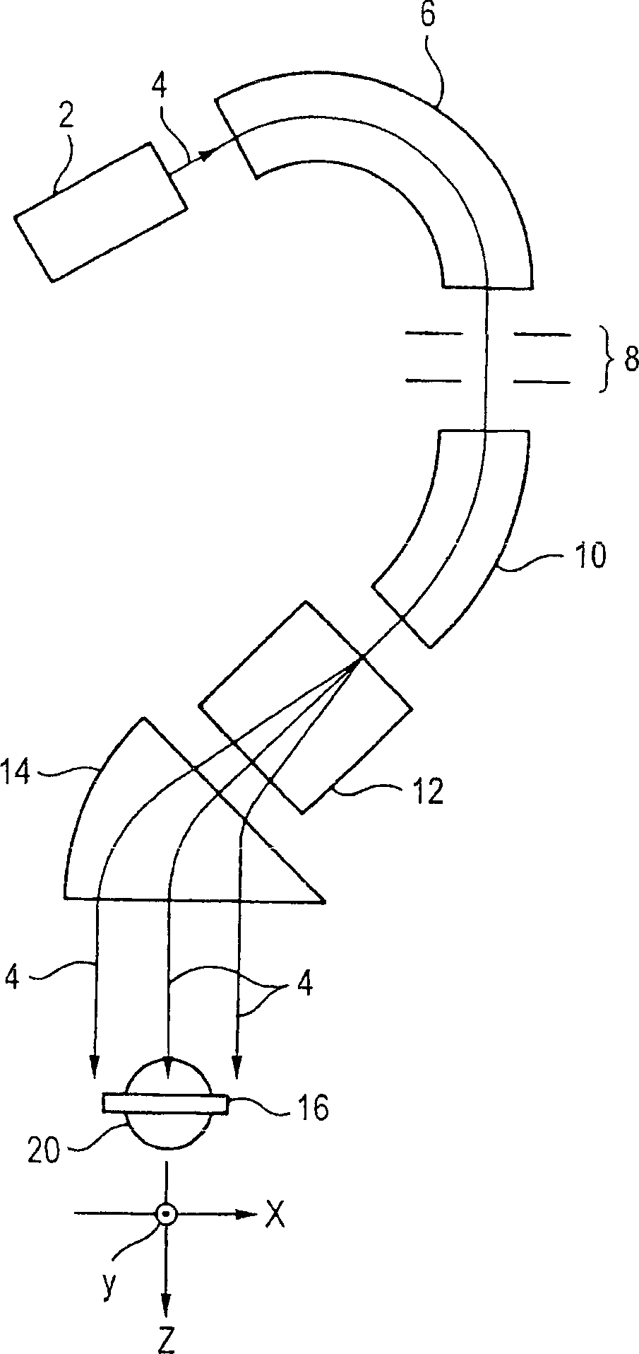
[0056] Figure 7 is a view showing an essential part of an embodiment of an ion implantation apparatus for realizing the ion beam measuring method according to the present invention. General structure reference of ion implantation equipment figure 1 and descriptions associated with it. Additionally, with figure 1 The same or corresponding parts in the illustrated examples are denoted by the same symbols, and in the following, differences from the above examples will be mainly explained.

[0057] The ion implanter includes a position z on the upstream side of the target 16 ff The foreground multipoint Faraday 24 and the position z on the downstream side of the target 16 fb The multi-point Faraday 24 in the background, the position is the position relative to the z-axis constituting the advancing direction of the ion beam 4 . The z-axis position of the target 16 is marked by z t express. When target 16 as Figure 7 When the example shown is tilted, the z-axis position of...


PUM


Abstract

A beam current density distribution in y direction of an ion beam 4 at a position of a forestage beam restricting shutter 32 is measured by measuring a change in a beam current of the ion beam 4 incident on a forestage multipoint Faraday 24 by passing an outer side of a side 34 of the shutter 32 while driving the forestage beam restricting shutter 32 in y direction by a forestage shutter driving apparatus 36. Further, a beam current density distribution in y direction of the ion beam 4 at a position of a poststage beam restricting shutter 42 is measured by measuring a change in the beam current of the ion beam 4 incident on a poststage multipoints Faraday 28 by passing an outer side of a side 44 of the shutter 42 while driving the poststage beam restricting shutter 42 in y direction by a poststage shutter driving apparatus 46. Further, at least one of an angle deviation, a diverging angle and a beam side in y direction of the ion beam 4 is measured by using a result of the measurement.

Description

technical field [0001] The present invention relates to an ion beam measurement method for measuring an angular deviation of an ion beam in a y direction perpendicular to an x ​​direction in an ion implantation device and an ion implantation apparatus capable of performing the test method by using a control device , divergence angle and beam size, the type of device is to scan the ion beam in parallel in the x-direction to impinge on the target. Background technique [0002] In recent years, ion implantation technology has played an important role in the semiconductor manufacturing process. [0003] When implanting ions into a target such as a semiconductor substrate, it is known that the implantation characteristics particularly in the implantation depth direction are determined by the implantation angle (incident angle) with respect to the crystal axis of the semiconductor substrate, and it is generally required that the ion implantation technique be able to prevent The i...

Claims


Application Information

Patent Timeline
Patent Type & Authority Applications(China)
IPC IPC(8): G01T1/29G21K1/04G21K5/04H01J37/04H01J37/244H01J37/317H01L21/265
CPCH01J37/244H01J37/3171H01J2237/24405H01J2237/2446H01J2237/24507H01J2237/31703H01L21/26586H01L21/265
Inventor 海势头圣滨本成显
Owner NISSIN ION EQUIP CO LTD
Why Eureka
Try Eureka