


Quick Research
Generate reliable direction feasibility study reports for your R&D in just a few steps.

Technical Q&A
Discover and master advanced knowledge NOW. Basics, ideas, possibilities, all at once.

Find Solutions
As an expert in R&D theories, this can generate solutions to your technical problems instantly.

Evaluate Feasibility
Analyze your overall solution with one click, know your potential R&D risks in advance.

Monitor Landscape
Get weekly tech updates, stay abreast of the latest tech innovations and key insights.
Super long alignment infrared focus plane detector
An infrared focal plane and detector technology, applied in the direction of electric solid-state devices, semiconductor devices, semiconductor/solid-state device components, etc. Stress-increasing, cost-reducing effects
- Summary
- Abstract
- Description
- Claims
- Application Information
AI Technical Summary
Problems solved by technology
Method used
Image

Examples
Embodiment Construction
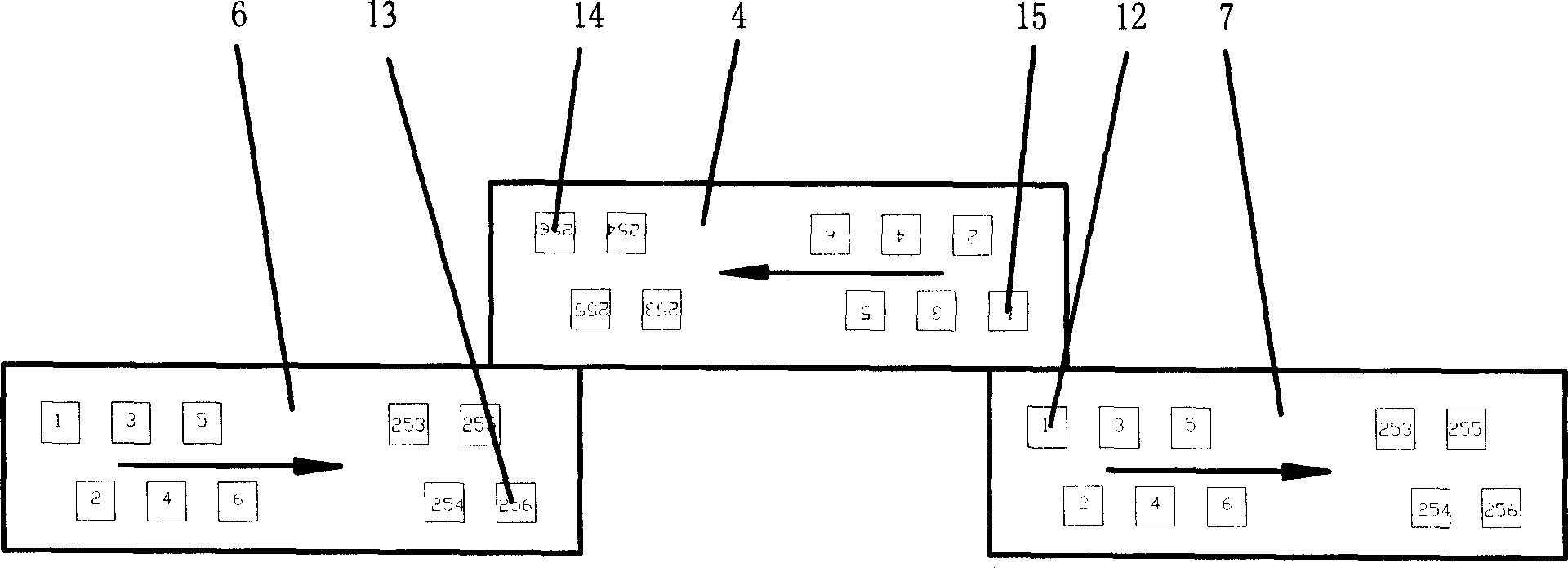
[0027] The specific embodiments of the present invention will be described in detail below with reference to the accompanying drawings, using a single-band 256×1 linear focal plane device as a sub-module:
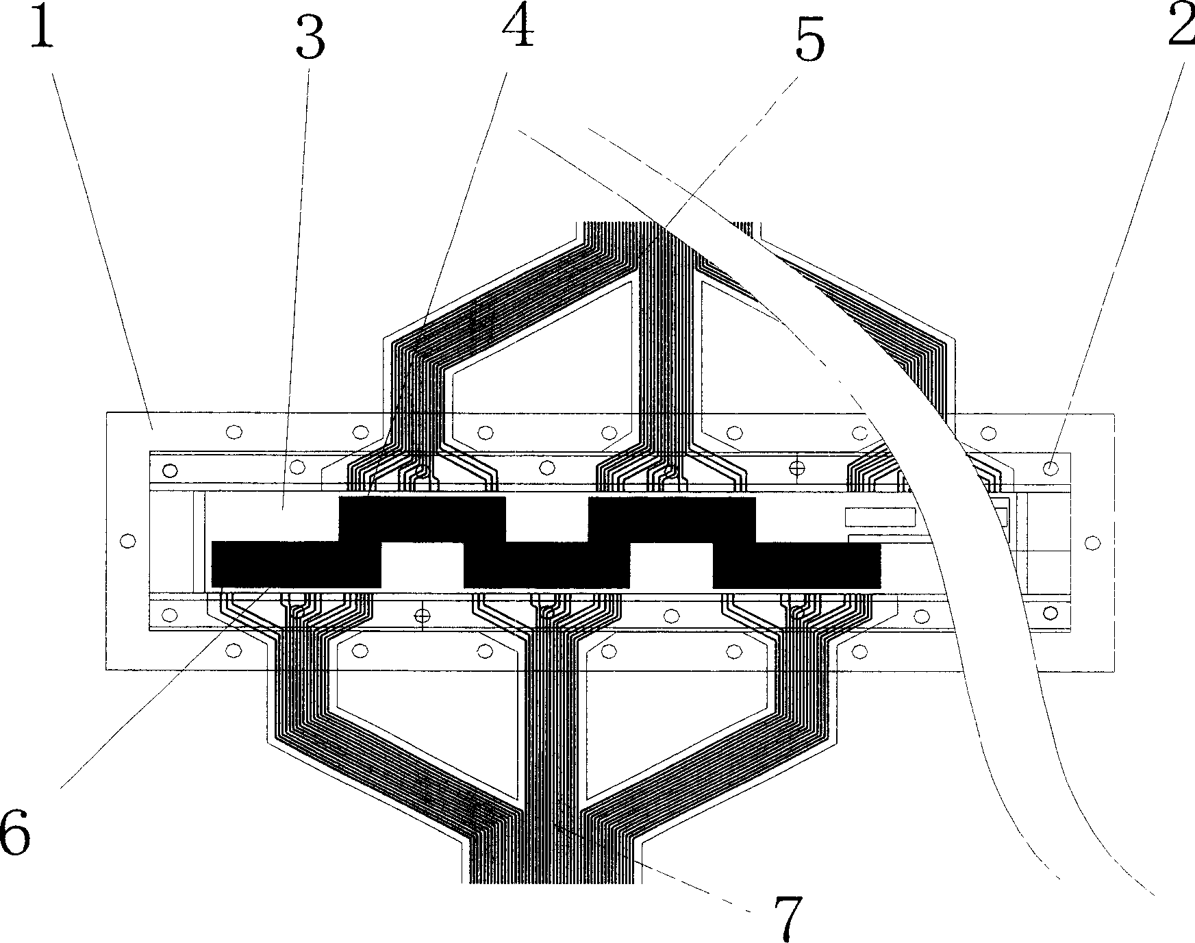
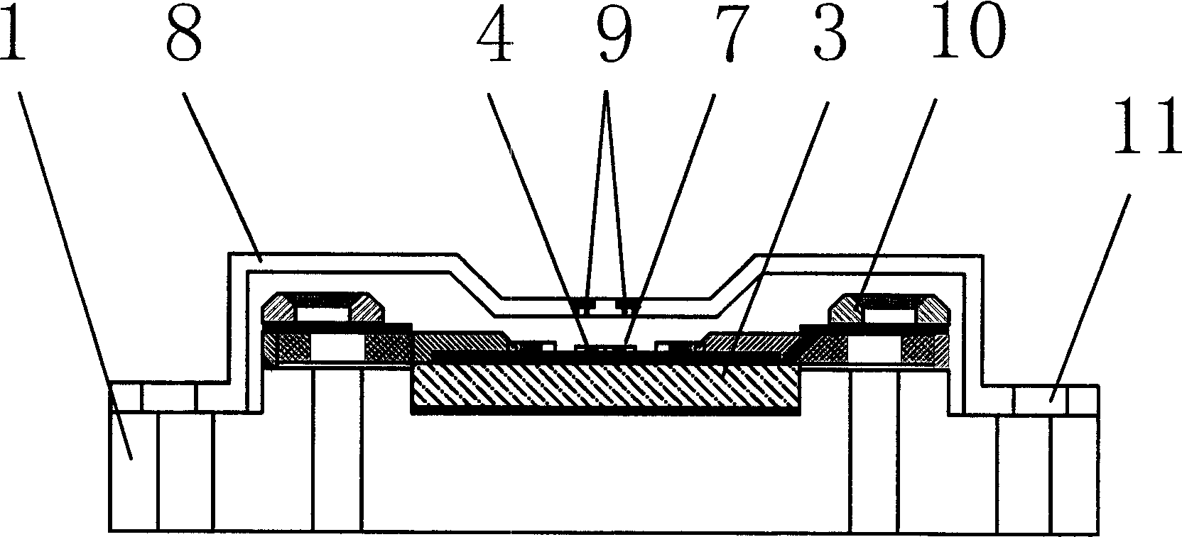
[0028] The ultra-long line focal plane device of the present invention consists of a splicing substrate 1 inlaid with a ceramic transition plate 3, an odd-numbered sub-module 6, an even-numbered sub-module 4, a cold filter window frame 8 with an optical filter 9, and an odd-numbered module outer lead strip 7. The even-numbered modules are composed of 5 and other components.
[0029] The splicing substrate 1 is made of a metal material with low thermal expansion coefficient and is inlaid with a ceramic transition plate 3. The surface parallelism and flatness of the splicing substrate and the ceramic transition plate are better than 0.005mm. There are a series of screw holes 2 necessary for installing cold filter window frame 8, outer lead straps 5, 7 and other parts on the s...
PUM
 Abstract
Description
Claims
Application Information
 - R&D Engineer
- R&D Manager
- IP Professional
- Industry Leading Data Capabilities
- Powerful AI technology
- Patent DNA Extraction
Browse by: Latest US Patents, China's latest patents, Technical Efficacy Thesaurus, Application Domain, Technology Topic, Popular Technical Reports.
© 2024 PatSnap. All rights reserved.Legal|Privacy policy|Modern Slavery Act Transparency Statement|Sitemap|About US| Contact US: help@patsnap.com