
Display and back light module

A technology for backlight modules and displays, applied in instruments, optics, nonlinear optics, etc., can solve the problems of unclean wiping process, complicated process, damage to backlight modules, etc.

Inactive Publication Date: 2006-11-08
HONG FU JIN PRECISION IND (SHENZHEN) CO LTD +1
View PDF0 Cites 4 Cited by
  • Summary
  • Abstract
  • Description
  • Claims
  • Application Information

AI Technical Summary

Problems solved by technology

[0003] After the display is used for a period of time, dust, oil, bacteria, etc. will adhere to the surface of the light source. Such dust and oil will affect the light energy irradiated by the light source to the light guide plate, thereby affecting the luminance and brightness uniformity

Method used


Image

  • Display and back light module
  • Display and back light module
  • Display and back light module

Examples


Example Embodiment

[0012] The present invention will be described in further detail below in conjunction with the accompanying drawings and specific embodiments.

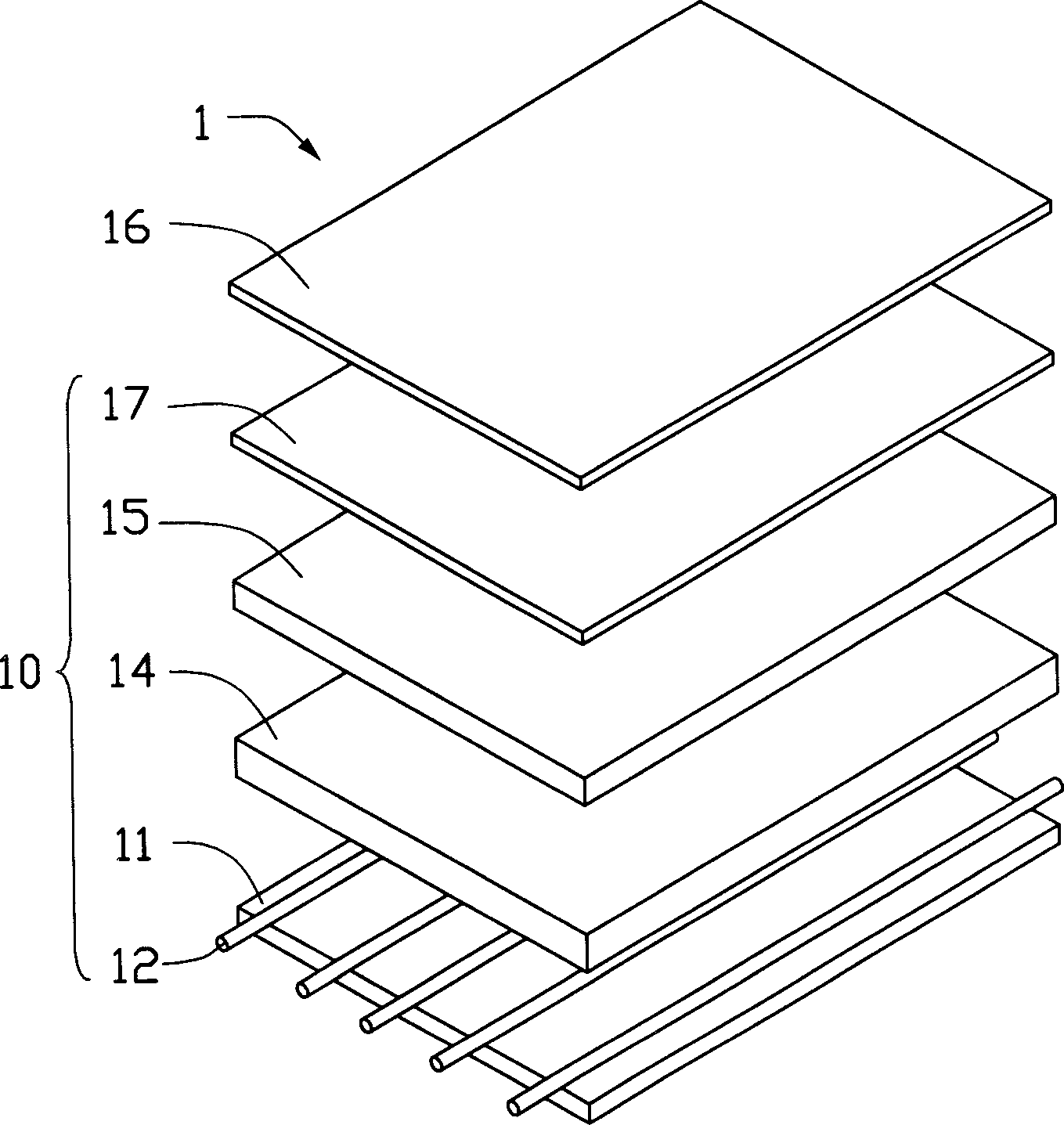
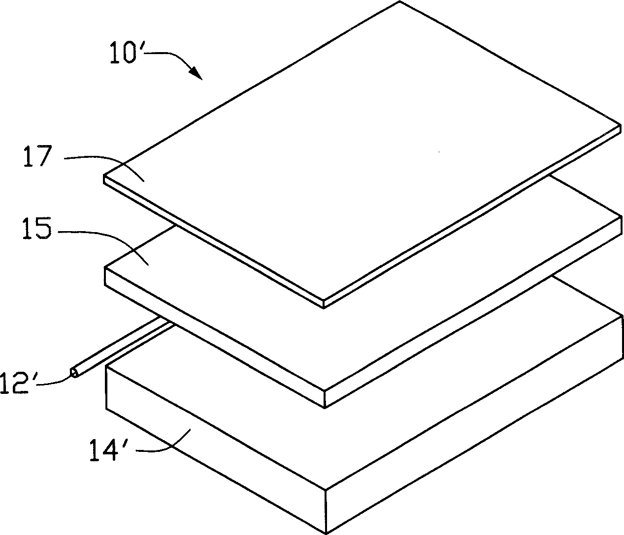
[0013] like figure 1 As shown, the display 1 includes a liquid crystal panel 16 and a backlight module 10, and the liquid crystal panel 16 and the backlight module 10 are fixed in a frame (not shown). Wherein, the backlight module 10 includes a light guide plate 14 , a plurality of light source devices 12 , a light source cover 11 , and a diffusion sheet 15 and a brightness enhancement sheet 17 disposed above the light guide plate 14 .

[0014] Wherein, the light source device 12 of the backlight module 10 is disposed under the light guide plate 14, which is called a direct-type structure. Since the number of light source devices 12 used in the direct-type structure backlight module 10 is generally more than two, the power consumption of the display 1 using the backlight module 10 is increased, and it is generally used in LCD monitor...


PUM

PropertyMeasurementUnit
Granularityaaaaaaaaaa
Thicknessaaaaaaaaaa

Abstract

A display includes a light source device, in which, a light-touch medium layer is distributed on the surface of said light source device and composed of TiO2 particles to sterilize and remove dust radiated by the light source device.

Description

【Technical field】 [0001] The invention relates to a plane display and a backlight module. 【Background technique】 [0002] The light source of the backlight module used in the liquid crystal display is mostly a cold cathode fluorescent lamp (Cold Cathode Fluorescent Lamp, CCFL), which belongs to a low pressure mercury discharge lamp. The light emitted by the light source is transmitted through the light guide plate of the backlight module and transmitted from the light guide plate, and the transmitted light is irradiated to the liquid crystal layer, and the liquid crystal layer achieves the purpose of development under the irradiation of light. Cold-cathode fluorescent lamps are coated with a layer of phosphor powder on the inner wall of the glass tube, and a small amount of inert gas and mercury are sealed inside the glass tube. During the mercury discharge, it is impacted by electrons to generate ultraviolet rays, which are converted into visible light when irradiated by th...

Claims


Application Information

Patent Timeline
IPC IPC(8): G02F1/1335G09F9/35
Inventor 简士哲
Owner HONG FU JIN PRECISION IND (SHENZHEN) CO LTD
Learn More