


Quick Research
Generate reliable direction feasibility study reports for your R&D in just a few steps.

Technical Q&A
Discover and master advanced knowledge NOW. Basics, ideas, possibilities, all at once.

Find Solutions
As an expert in R&D theories, this can generate solutions to your technical problems instantly.

Evaluate Feasibility
Analyze your overall solution with one click, know your potential R&D risks in advance.

Monitor Landscape
Get weekly tech updates, stay abreast of the latest tech innovations and key insights.
Electromagnetic wave generating device
A technology for generating devices and electromagnetic waves, applied in electrical components, magnetic induction accelerators, magnetic resonance accelerators, etc., can solve problems such as unstable rotation, difficulty in repeatedly colliding with targets, and limitations in applicable fields
- Summary
- Abstract
- Description
- Claims
- Application Information
AI Technical Summary
Problems solved by technology
Method used
Image

Examples
Embodiment approach 1
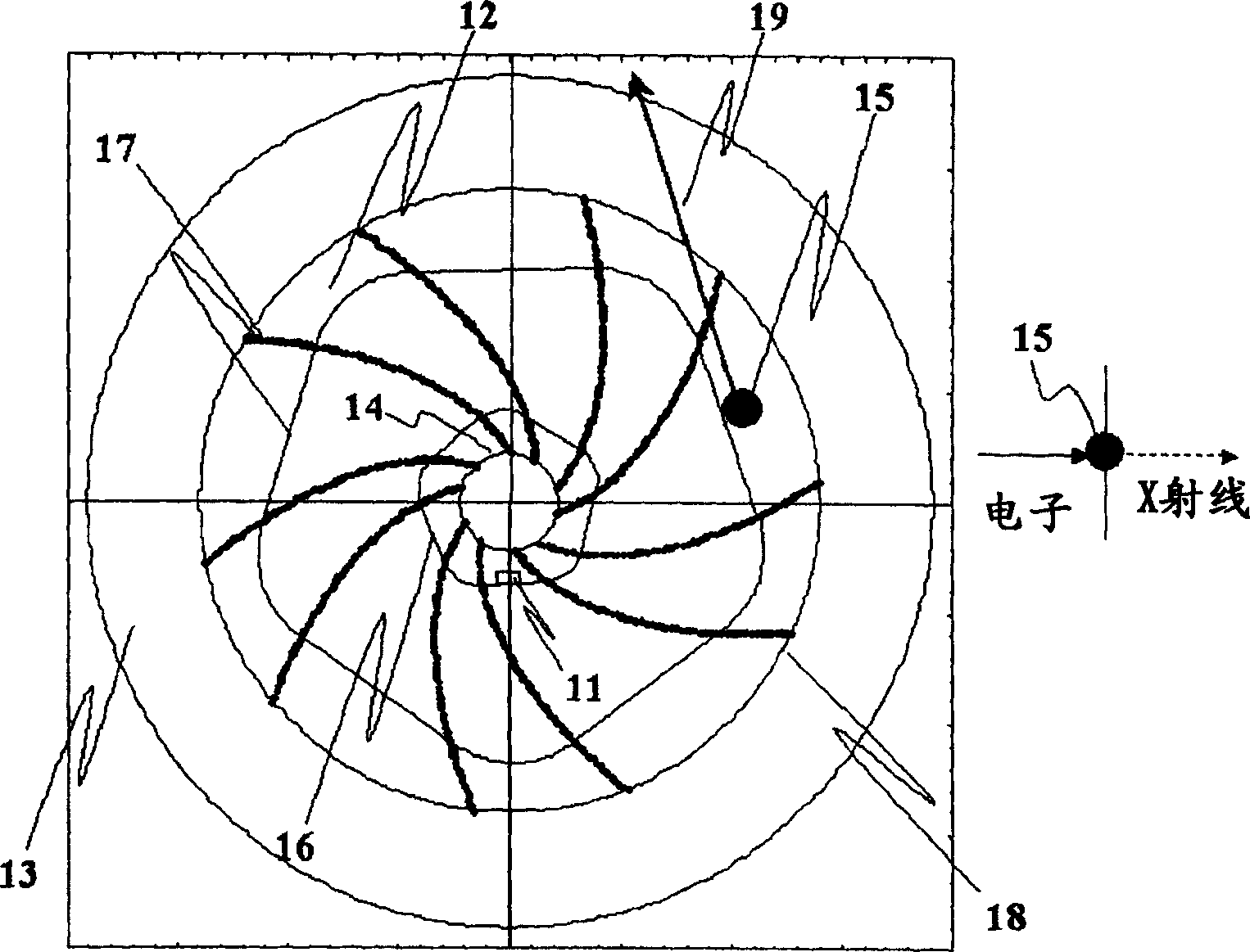
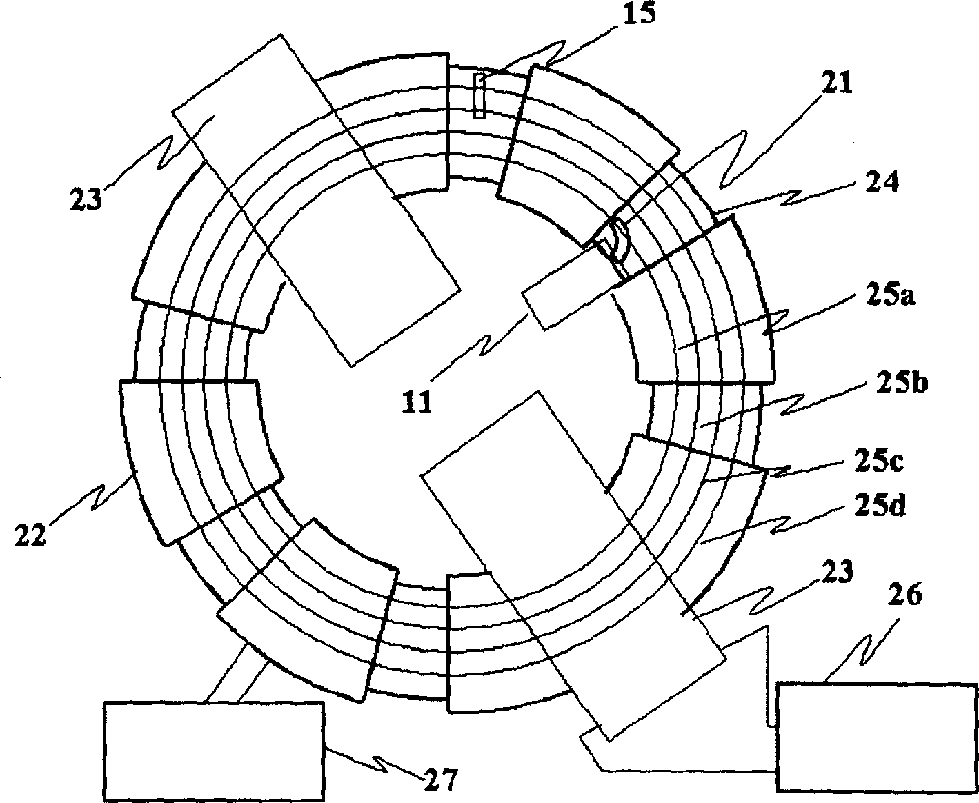
[0020] figure 1 , figure 2 It is a figure which respectively shows the configuration example 1 and the configuration example 2 of the electromagnetic wave generator of Embodiment 1. No matter which example is using the AG (Alternatig Gradient) focused accelerator ( figure 1 According to non-patent literature 2 (H.Tanaka, T.Nakanishi, "DESIGNAND CONSTRUCTION OF A SPIRAL MAGNET FOR A HYBRIDACCELERATOR", Proceedings of the 1st Annual Meeting of Particle Accelerator Society of Japan and the 29th Linear Accelerator Meeting in Japan (August4-6, 2004 , Funabashi Japan), 465p-467p), figure 2 This point is common to Patent Document 2 (Patent Publication No. 2004-296164), and a high-performance electromagnetic wave generator can be realized by performing predetermined control that exhibits its characteristics.
[0021] exist figure 1 Among them, 11 is an electron generating unit that generates electron beams, and 12 is a spiral magnetic pole that sandwiches the electron beam trave...
Embodiment approach 2
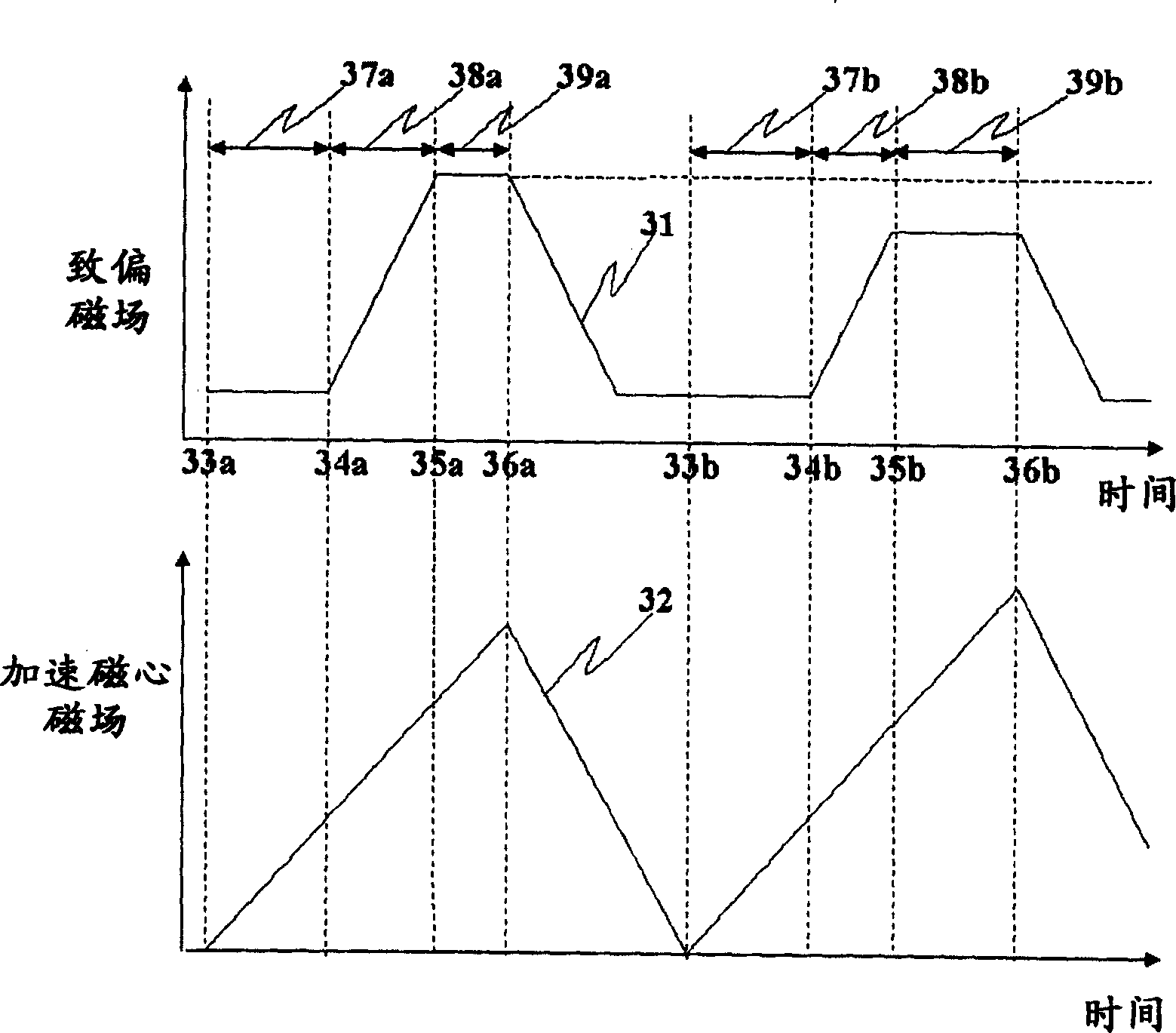
[0053] This embodiment is a form in which the degree of expansion in the radial direction of the orbit of the electron beam at the time of incidence is increased compared to the case of the first embodiment. Figure 5 An example of a time-varying model of the biasing magnetic field and the accelerating core magnetic field in this case is shown. In the figure, the parts with the same number and image 3 same as the description. Figure 5 The example of the 1st electron incident is to take the time variation 31 of the biasing magnetic field as a certain example in the whole process. In this case, the accelerated electron beam expands more than image 3 The situation is even bigger. Figure 5 The example of the second incident electrons is an example in which the bias magnetic field is reduced at the time of incident electron beams. In this case, the expansion of the electron beam accompanying the acceleration in the radial direction of the orbit becomes larger than when the ...
Embodiment approach 3
[0055] Embodiment 3 is a mode in which high-speed switching of the energy of generated X-rays is realized by changing the energy of electron beams at high speed without re-incidence of electrons. Image 6 An example of a time-varying model of the biasing magnetic field and the accelerating core magnetic field in this case is shown. Instructions from 31 to 39a in Figures and image 3 same situation. Here, 36a indicates the start time of the electron beam re-acceleration time 43a corresponding to the electron beam acceleration time 38a while indicating the end time of the constant deflection magnetic field control. 41a is not only the end time of the electron beam re-acceleration time 43a, but also the start time of the target re-collision time 44a corresponding to the target collision time 39a. Then, 42a is the end time of the target re-collision time 44a.
[0056] The operation will be described below.
[0057] The process from time 33a to 36a and image 3 The situation i...
PUM
 Abstract
Description
Claims
Application Information
 - R&D Engineer
- R&D Manager
- IP Professional
- Industry Leading Data Capabilities
- Powerful AI technology
- Patent DNA Extraction
Browse by: Latest US Patents, China's latest patents, Technical Efficacy Thesaurus, Application Domain, Technology Topic, Popular Technical Reports.
© 2024 PatSnap. All rights reserved.Legal|Privacy policy|Modern Slavery Act Transparency Statement|Sitemap|About US| Contact US: help@patsnap.com