
Workpiece transport device

A technology for conveying devices and workpieces, which can be used in conveyors, metal processing, manufacturing tools, etc., and can solve problems such as transmission speed limitations

Inactive Publication Date: 2006-11-01
豪迈木材加工系统公司
View PDF2 Cites 1 Cited by
  • Summary
  • Abstract
  • Description
  • Claims
  • Application Information

AI Technical Summary

Problems solved by technology

However, the achievable transfer speed is limited by the unavoidable friction between the slide rail and the workpiece

Method used


Image

  • Workpiece transport device

Examples


Embodiment Construction

[0017] Preferred embodiments of the present invention will be described in detail below with reference to the accompanying drawings.

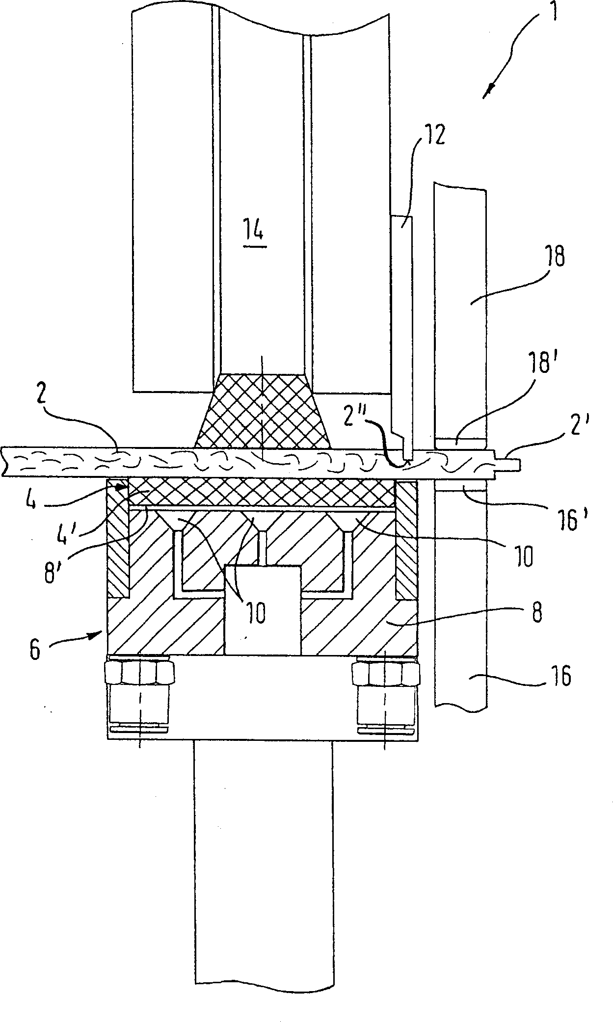
[0018] figure 1 A side view of a workpiece transfer device 1 as a preferred exemplary embodiment of the present invention is schematically shown. The workpiece transfer device 1 is used to transfer flat workpieces 2 to be processed during their passage through a forming machine designed to provide the exposed sides 2' of the workpieces 2 with, for example, tenons and grooves or "detents". "Forming processing of engaging elements such as.

[0019] figure 1 The workpiece transfer device 1 shown comprises an endless endless conveyor belt 4, figure 1 Only the upper strand 4' of the belt is shown, which is designed to store and transport the workpieces 2 to be transported by means of friction. The conveyor belt 4 is guided on a fixed guide 6 having a guide rail 8 holding the upper strand 4' along the conveyor track. The guide rail 8 has on its ...


PUM


Abstract

A stationary linear guide fin (12), attached to one side of a pressing mechanism (14), engages a guide groove (2") cut on the upper surface of a workpiece (2). A workpiece supporting skid (16) is located beside a transportation belt (4) on which the workpiece is moved.

Description

technical field [0001] The invention relates to a workpiece conveying device for a machine tool. Background technique [0002] A workpiece transport device for machine tools is known, for example, from EP 1 516 697 A2, which has an endless circulating transport belt and fixed guides for guiding the belt; wherein the workpieces are held by means of friction and / or shape On the upper strand (upperstrand) of the conveyor belt, the guide has a guide rail holding said upper strand along the conveying track, which guide rail has on its upper side a channel (channel) shaped to fit the belt, the guide also There is a base body in which there are air outlets connected to a source of compressed air. [0003] Such workpiece transfer devices are used in particular when machining the narrow sides of narrow plate-shaped workpieces, such as laminated or ready-made parquet panels, for example, with engaging elements such as tenons and grooves or "clicks" During the process, transfer these...

Claims


Application Information

Patent Timeline
IPC IPC(8): B23Q7/00B65G15/60B65G15/64
CPCB27C5/06B27F5/026B65G15/60
Inventor 阿克姆·高斯彼得·瑞斯盖博
Owner 豪迈木材加工系统公司
Learn More