
Image display device

A display device and image technology, applied in image communication, electrical components, stereo systems, etc., can solve problems such as crosstalk, shading, and poor luminous efficiency

Active Publication Date: 2006-10-25
KONINKLIJKE PHILIPS ELECTRONICS NV
View PDF0 Cites 14 Cited by
  • Summary
  • Abstract
  • Description
  • Claims
  • Application Information

AI Technical Summary

Problems solved by technology

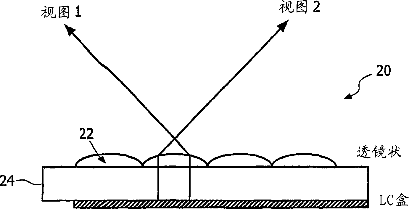
Again, the disadvantages of this device are the small viewing areas 36, 38 and the large amount of crosstalk 40
In addition, such devices have poor luminous efficiency because the shield blocks a large amount of light

Method used


Image

  • Image display device
  • Image display device
  • Image display device

Examples


no. 2 example

[0075] For the second embodiment, the individual angles can be calculated as follows:

[0076] α j = arctan ( - w 2 + b 2 - jp )

[0077] β j = arctan ( w 2 - b 2 - ( j - 1 ) p ) - - - ( 3 )

[0078] For j=...,-2,-1,2,3,...

[0079] Likewise, refraction occurs on surfaces from glass to air. This refraction produces the following angles:

[0080] ...


PUM


Abstract

A display device comprising a display panel (62) having a plurality of separately addressable pixels (64) for displaying an image, a first group (64a) of said pixels being configured to provide emergent light in a first polarisation state (P), and a second group (64b) of said pixels being configured to provide emergent light in a second polarisation state (S), a barrier layer (68) in optical association with the display panel to partially occlude said emergent light, the barrier layer having a first plurality of regions (72) for passing light in one of the first or second polarisation states, and a second plurality of regions (74) for passing light in the other of the first and second polarisation states and a third plurality of regions (76) for occluding said emergent light, and wherein the first (72) and second (74) regions of the barrier layer are respectively registered with the first (64a) and second (64b) groups of pixels so as to provide different views of an image displayed by said display panel.

Description

technical field [0001] The present invention relates to image display devices, and in particular to multi-view display devices, wherein each user of a plurality of users is able to see a different image than one or more other users. Background technique [0002] Generating three-dimensional images generally requires a display device capable of providing different views to the left and right eyes of a user of the display device. This effect is achieved by providing individual images directly to each eye of the user, using specially configured glasses. In one example, the display provides alternating left and right views in a timed fashion, which views can be brought into the viewer's respective eyes using synchronized viewing glasses. [0003] In contrast, the present invention relates to multiple types of display devices in which different views of an image can be observed depending on the viewing angle relative to a single display panel. Hereinafter, these devices are gen...

Claims


Application Information

Patent Timeline
IPC IPC(8): H04N13/04
Inventor W·L·伊泽尔曼C·多恩坎普
Owner KONINKLIJKE PHILIPS ELECTRONICS NV
Learn More