
Adjustable bed

a technology of adjustable beds and bedsores, applied in the field of adjustable beds, can solve the problems of affecting the care of the recipient, the positional relationship between the motion centers of the bed and the recipient's body, and placing a large burden on the caregiver, and achieve the effects of increasing linear distance, and reducing the occurrence of bedsores

Inactive Publication Date: 2005-04-14
SANYO ELECTRIC CO LTD
View PDF10 Cites 30 Cited by
  • Summary
  • Abstract
  • Description
  • Claims
  • Application Information

AI Technical Summary

Benefits of technology

[0012] An object of the present invention, which was arrived at in view of the above problems, is to provide an adjustable bed that is not only usable as a low platform bed suited to care recipients, but also prevents the occurrence of bedsores and the like, and enables excellent Gatch actions to be performed that take account of the motion center of the care recipient's body.
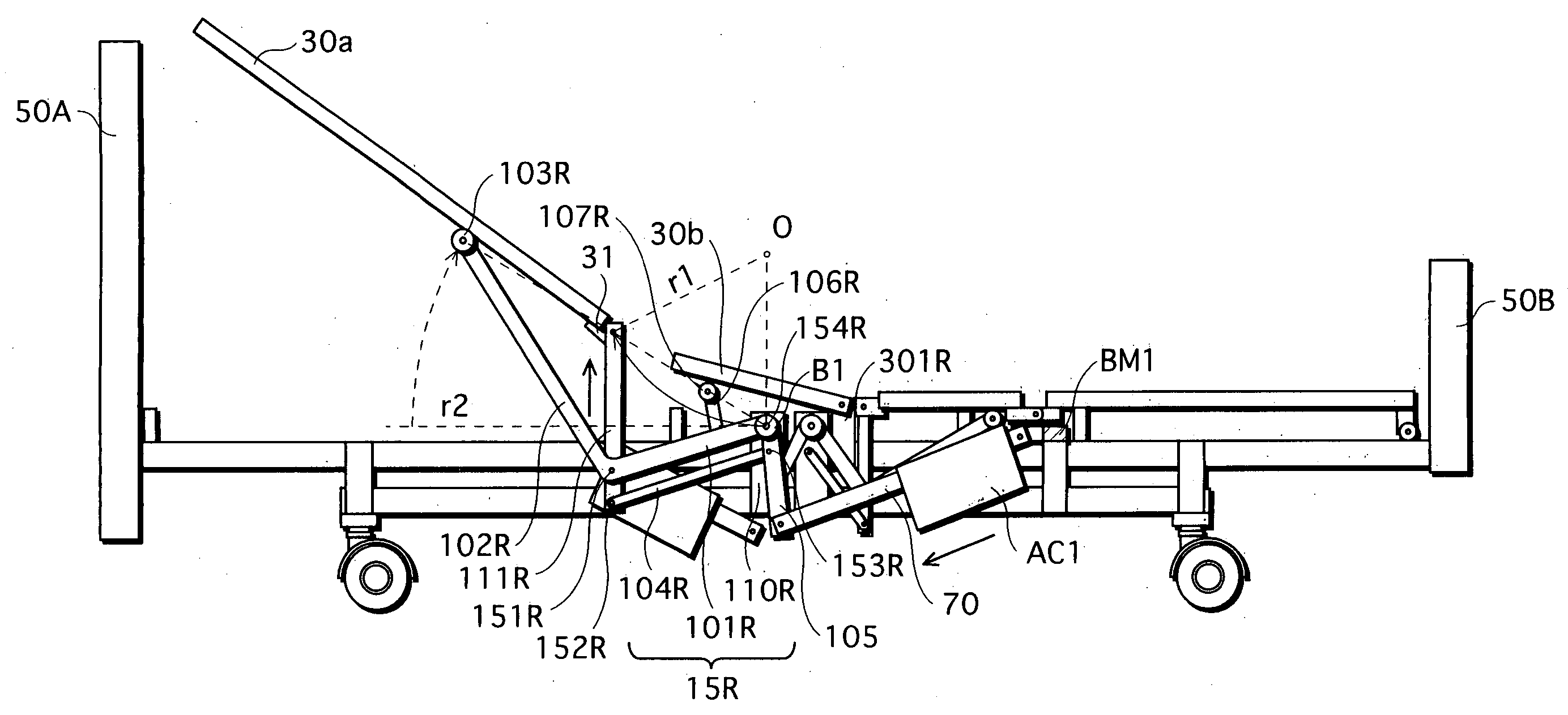
[0018] According to an adjustable bed of the present invention having the above structure, the second arm group is elevated upward while maintaining the intersection angle of the reference bed surface, due to the operation of the parallel link mechanism within the Gatch mechanism when the bed is driven. This causes the part coupling the first surface member to the second arm group to rise up in a circular motion around an imaginary rotation center located a prescribed distance above the surface of the second surface member. The location of the imaginary rotation center near the motion center (e.g. a predetermined joint) of the care recipient's body when flexed, allows the adjustable bed to move in sympathy with the body's motion center (i.e. motion center of sitting-up or knee-break action).
[0019] Thus, with the adjustable bed of the present invention, if the first surface member is set as the upper-back platform, slippage of the care recipient's body in relation to the surface of the upper-back platform is prevented when the sitting-up action is performed, thereby suppressing the occurrence of bedsores and realizing a natural sitting-up action (i.e. postural change from lying to sitting position) that takes account of the care recipient's body movement.
[0020] Furthermore, a major feature of the adjustable bed of the present invention is the ability to increase the angle of the first surface member with respect to the reference bed surface when the bed is driven, in proportion to the length of the support arm. That is, in order to raise the first surface member more dynamically, the support arm can be lengthened so as to increase the linear distance from the tip of the support arm to the pivotal coupling point of the first and second arm groups. Because the support arm lies in the longitudinal direction of the bed, increasing the linear distance from the tip of the support arm to the pivotal coupling point does not require the platform surface height of the adjustable bed to be increased, thereby enabling the platform surface to be kept at a low height.
[0021] Since the provision of a conventional large-scale Gatch mechanism in a lower part of the bed is not necessary to obtain an excellent Gatch action, the adjustable bed of the present invention has the merit of being usable as a so-called low platform bed having a low platform surface. The adjustable bed of the present invention is thus able to lighten the caregiver's workload, in addition to being usable as an extremely safe nursing care bed.

Problems solved by technology

However, with adjustable beds such as the above Gatch bed, usually the motion center of the person (e.g. care recipient) lying on the platform surface when performing a sitting-up or knee-break action does not correspond to the motion center of the bed (i.e. coupled position of the upper and lower body platforms), meaning that a displacement exists in the positional relationship between the motion centers of the bed and the care recipient's body.
The shearing and frictional forces work against one another due to the care recipient's body weight, causing problems such as the following.
This places a large burden on the caregiver particularly when the sitting-up action is performed, since the caregiver is required to pull the care recipient's body back up from where it has slipped down in relation to the surface of the upper-body platform.
Moreover, with extended use of the bed, the shearing and frictional forces are exerted on the care recipient's body every time a Gatch action is performed, the accumulation of which places a burden on the body.
A similar problem also occurs when the lower-body platform is raised from the horizontal bed position to perform the knee-break action.
While such problems have led to steps currently being taken to align the Gatch bed's motion center as near as possible to that of the care recipient, the height of the platform surface in the prior art is generally raised when a bed is equipped with a Gatch mechanism, making it difficult to construct low platform beds suited to care recipients.
However, maintaining the length of this perpendicular arm raises the platform surface by a corresponding amount, making it difficult to structure the disclosed bed as a low platform bed.

Method used


Image

  • Adjustable bed
  • Adjustable bed
  • Adjustable bed

Examples


embodiment 1

[0033] 1-1. Overall Structure of Adjustable Bed

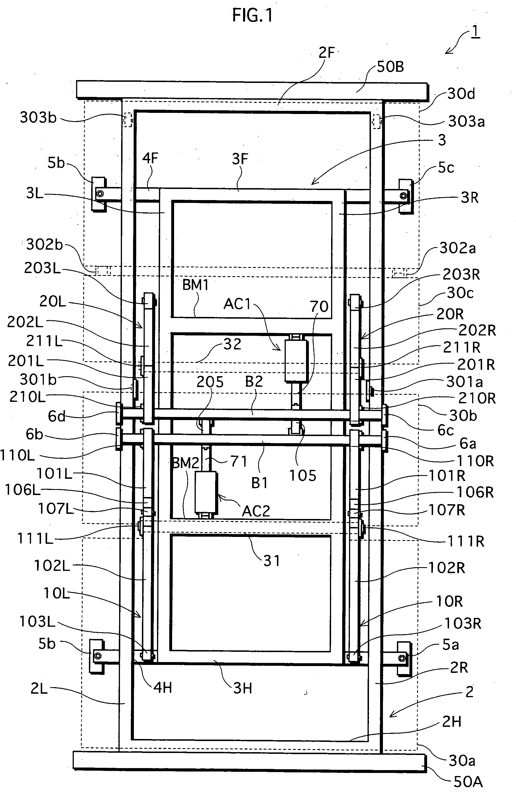
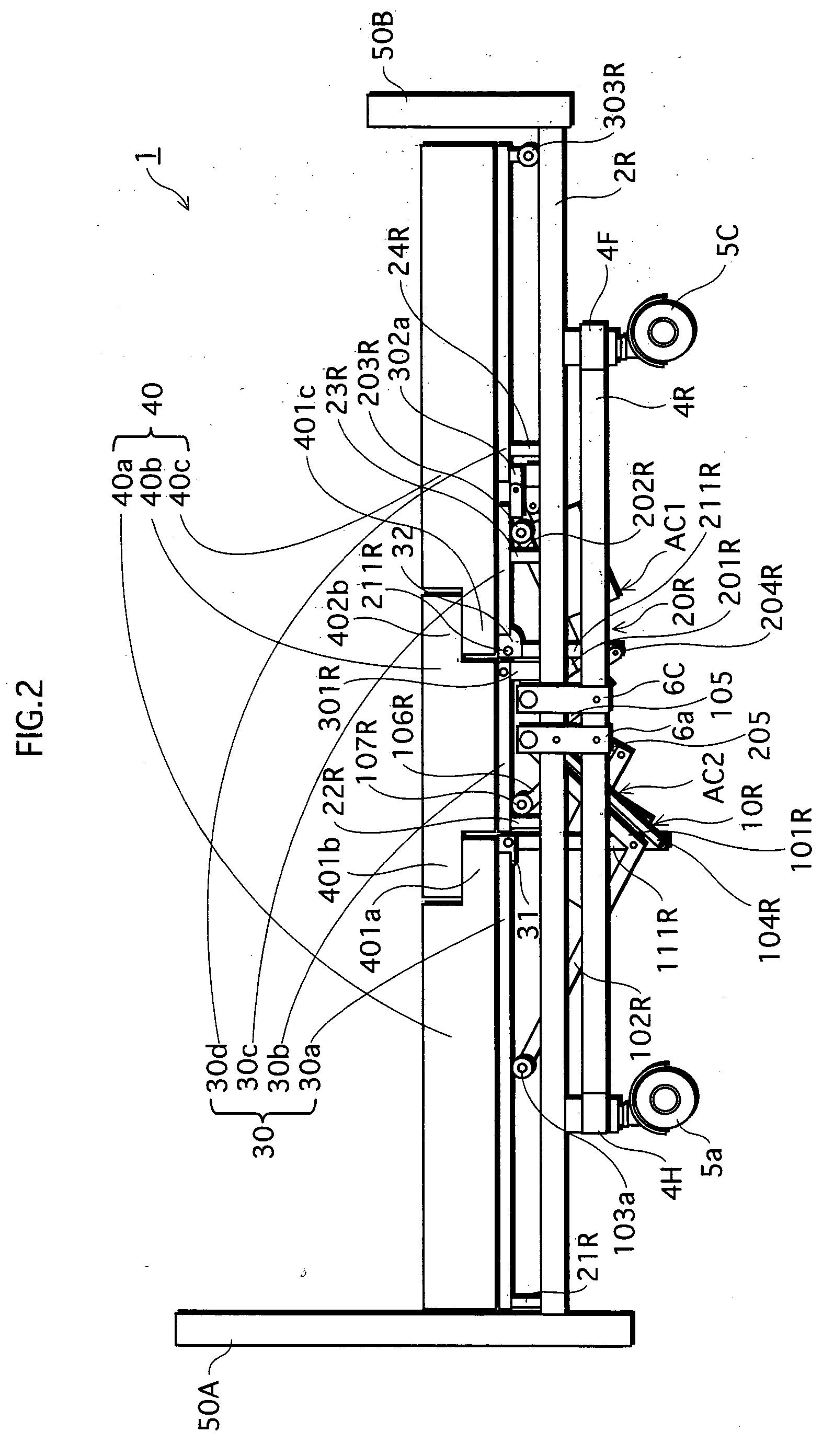
[0034]FIG. 1 is a plan view showing the structure of an adjustable bed 1 pertaining to embodiment 1. FIG. 2 is a side view of adjustable bed 1.

[0035] As shown in FIG. 1, adjustable bed 1 has a structure in which two rectangular frames 2 and 3 (first frame 2 and second frame 3) overlap concentrically.

[0036] First frame 2, which is larger than second frame 3, is formed from lengthwise beams 2R and 2L lying in a longitudinal direction of the bed, and cross beams 2H and 2F lying in a width direction of the bed. Boards 50A and 50B are disposed on cross beams 2H and 2F, respectively.

[0037] Second frame 3 is, similar to the first frame, formed from lengthwise beams 3R and 3L lying in the longitudinal direction, and cross beams 3H and 3F lying in the width direction. Two beams BM1 and BM2 lying parallel to cross beams 3H and 3F are disposed within the area of second frame 3, and actuators AC1 and AC2 are coupled respectively to beams BM1 an...

embodiment 2

[0102] 2-1. Overall Structure of Adjustable Bed

[0103]FIG. 8 is a side view showing the systematic structure of an adjustable bed 1000 pertaining to embodiment 2. FIG. 9 is an operation diagram of adjustable bed 1000. Plates 6a and 6c etc have been omitted here in order to simplify the internal structure of adjustable bed 1000.

[0104] As shown in FIG. 8, adjustable bed 1000 differs from adjustable bed 1 by virtue of the fact that parallel link mechanisms 50R / 50L and 60R / 60L (50L and 60L not depicted) equating to parallel link mechanisms 15R / 15L and 25R / 25L, also include pantograph mechanisms that provide extendibility in the longitudinal direction of the bed.

[0105] Specifically, as shown in FIG. 8, parallel link mechanism 50R is formed from the combination of three perpendicular arms 6b (plate fixed to frame 2), 501R and 111R constituting one group, and three moving arms 502R, 101R and 104R constituting another group.

[0106] Of these, perpendicular arms 6b / 501R and moving arms 101R...


PUM


Abstract

An adjustable bed that enables a Gatch mechanism to be operated in an excellent fashion to match the flexing of a care recipient's body, and that is, moreover, useable as a superior low platform bed for care recipients. To this end, a parallel link mechanism having a pair of perpendicular arms is provided in the adjustable bed as part of a sitting-up mechanism, and by always keeping these arms in a perpendicular position, the sitting-up mechanism is operated with a position removed from the surface of a lower-back board by a prescribed interval as an imaginary rotation center when the bed is driven. This prevents any slippage of the care recipient's body in relation to the platform surface, thereby suppressing the occurrence of bedsores and realizing a natural sitting-up action that takes account of the care recipient's body movement.

Description

BACKGROUND OF THE INVENTION [0001] 1. Field of the Invention [0002] The present invention relates to adjustable beds used in nursing care and the like, and in particular to improving controls for changing the posture of care recipients and so forth lying on the bed. [0003] 2. Related Art [0004] Gatch beds having so-called Gatch mechanisms for performing sitting-up and knee-break actions and so forth by flexing the platform surface of the bed longitudinally are a widely known type of adjustable bed. With a Gatch bed, as disclosed in Japanese Published Patent Application No. 2000-135146, the platform surface is partitioned into an upper-body (i.e. includes upper and lower back) platform and a lower-body (i.e. includes upper and lower legs) platform that are linked together, with the Gatch mechanism being operated by manually or mechanically raising the upper and / or lower-body platforms to a prescribed angle from a reference bed surface (generally, “horizontal bed surface”). [0005] How...

Claims


Application Information

Patent Timeline
Patent Type & Authority Applications(United States)
IPC IPC(8): A61G7/015
CPCA61G7/015
Inventor TAGUCHI, KENJIMORIKAWA, MASASHI
Owner SANYO ELECTRIC CO LTD
Learn More