Light emitting device and display device
A technology of a light-emitting device and a light-emitting part, which can be applied to static indicators, instruments, etc., can solve the problems of increased power consumption and increased power consumption loss.
- Summary
- Abstract
- Description
- Claims
- Application Information
AI Technical Summary
Problems solved by technology
Method used
Image

Examples
no. 1 approach
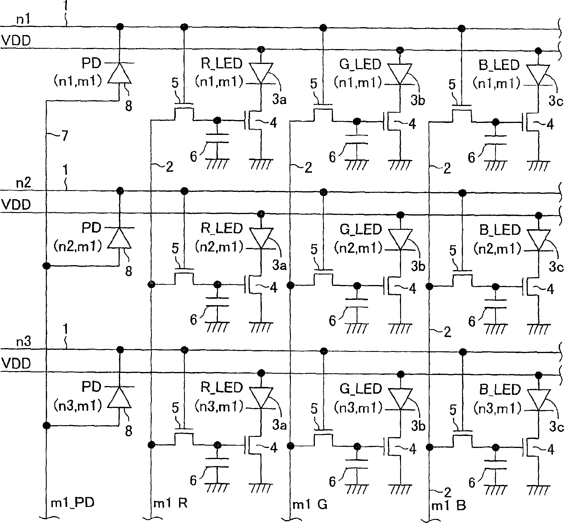
[0020] In the light-emitting device of this embodiment, if figure 1 As shown, on a substrate not shown, n scanning lines 1 substantially parallel to each other and m data lines 2 substantially parallel to each other cross each other, and their intersections are formed in n×m matrix. The aforementioned n and m are positive integers, and may be different or the same. Also, power supply lines VDD for respectively supplying power supply currents to light emitting diodes (hereinafter referred to as LEDs) 3 a , 3 b , and 3 c described later are provided along the scanning lines 1 .
[0021] At the aforementioned intersection point, red LEDs 3 a , green LEDs 3 b , and blue LEDs 3 c are sequentially and alternately arranged along the scanning line 1 . The anodes of the respective LEDs 3a, 3b, and 3c are connected to corresponding power supply lines VDD, respectively. Examples of the material of the red LED 3a include InGaAlP or GaAlAs, examples of the material of the green LED 3b i...
no. 2 approach
[0033] Such as figure 1 As shown, in this second embodiment, in addition to the above-mentioned first embodiment, each group of adjacent LEDs 3a, 3b, 3c is provided with a method for measuring the brightness of at least one of the above-mentioned LEDs 3a, 3b, 3c. The photodiode (photodetector) 8. The photodiode 8 is connected to the scan line 1 corresponding to its cathode, and the anode of the photodiode 8 is connected to the light detection line 7 arranged along the data line 2 . Therefore, when the scanning line 1 becomes high level and at least one of the LEDs 3a, 3b, 3c connected to the scanning line 1 emits light, the light emission luminance of each LED 3a, 3b, 3c that emits light can be detected.
[0034] Thus, in the second embodiment, when the light output changes due to deterioration of LED luminance, etc., by mounting the photodiode 8, each of the R, G, and B LEDs 3a, 3b, and 3c can be made to emit light (lighting) individually. ), by detecting the luminous outp...
no. 3 approach
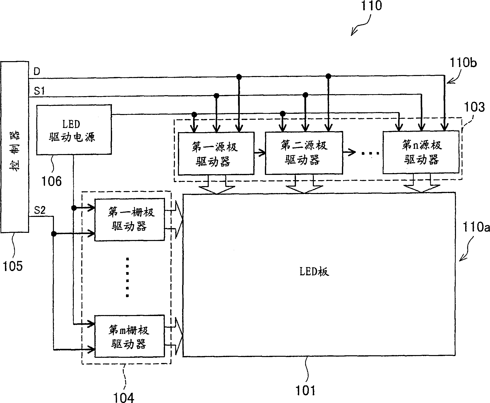
[0036] based on figure 2 A display device using the light-emitting device of the present invention as a third embodiment of the present invention will be described. Such as figure 2 As shown, it includes an active matrix (active matrix) type display device 110, an LED display portion 110a, and a driving circuit 110b for driving it.
[0037] The LEDs 3a, 3b, and 3c in the above-mentioned LED display portion 110a are arranged in a matrix (grid) as pixels (pixels), for example, 1024×768 points, based on image data, for each horizontal scanning line (line) sequentially or at intervals. displayed vertically so that images can be displayed. In the case of the above number of dots, the total number of horizontal scanning lines is 768, and one horizontal scanning line is 1024 dots. As the respective numbers of pixels, 1280×1024 dots, 1600×1200 dots, 3200×2400 dots, etc. are used as necessary.
[0038] On the other hand, a source driver 103 and a gate driver 104 constituted by an...
PUM
 Abstract
Description
Claims
Application Information
 - Generate Ideas
- Intellectual Property
- Life Sciences
- Materials
- Tech Scout
- Unparalleled Data Quality
- Higher Quality Content
- 60% Fewer Hallucinations
Browse by: Latest US Patents, China's latest patents, Technical Efficacy Thesaurus, Application Domain, Technology Topic, Popular Technical Reports.
© 2025 PatSnap. All rights reserved.Legal|Privacy policy|Modern Slavery Act Transparency Statement|Sitemap|About US| Contact US: help@patsnap.com