
Head suspension

A magnetic head and suspension technology, applied in the direction of supporting head, configuration/installation of recording head, structure of arm parts, etc.

Active Publication Date: 2006-10-18
NHK SPRING CO LTD
View PDF0 Cites 0 Cited by
  • Summary
  • Abstract
  • Description
  • Claims
  • Application Information

AI Technical Summary

Problems solved by technology

[0024] An object of the present invention is to solve the problem of a head suspension having a thin load beam to satisfy required shock characteristics: it is necessary to expand the width of the base end side of the load beam to increase the elastic load of the elastic member

Method used


Image

  • Head suspension
  • Head suspension
  • Head suspension

Examples


no. 1 example

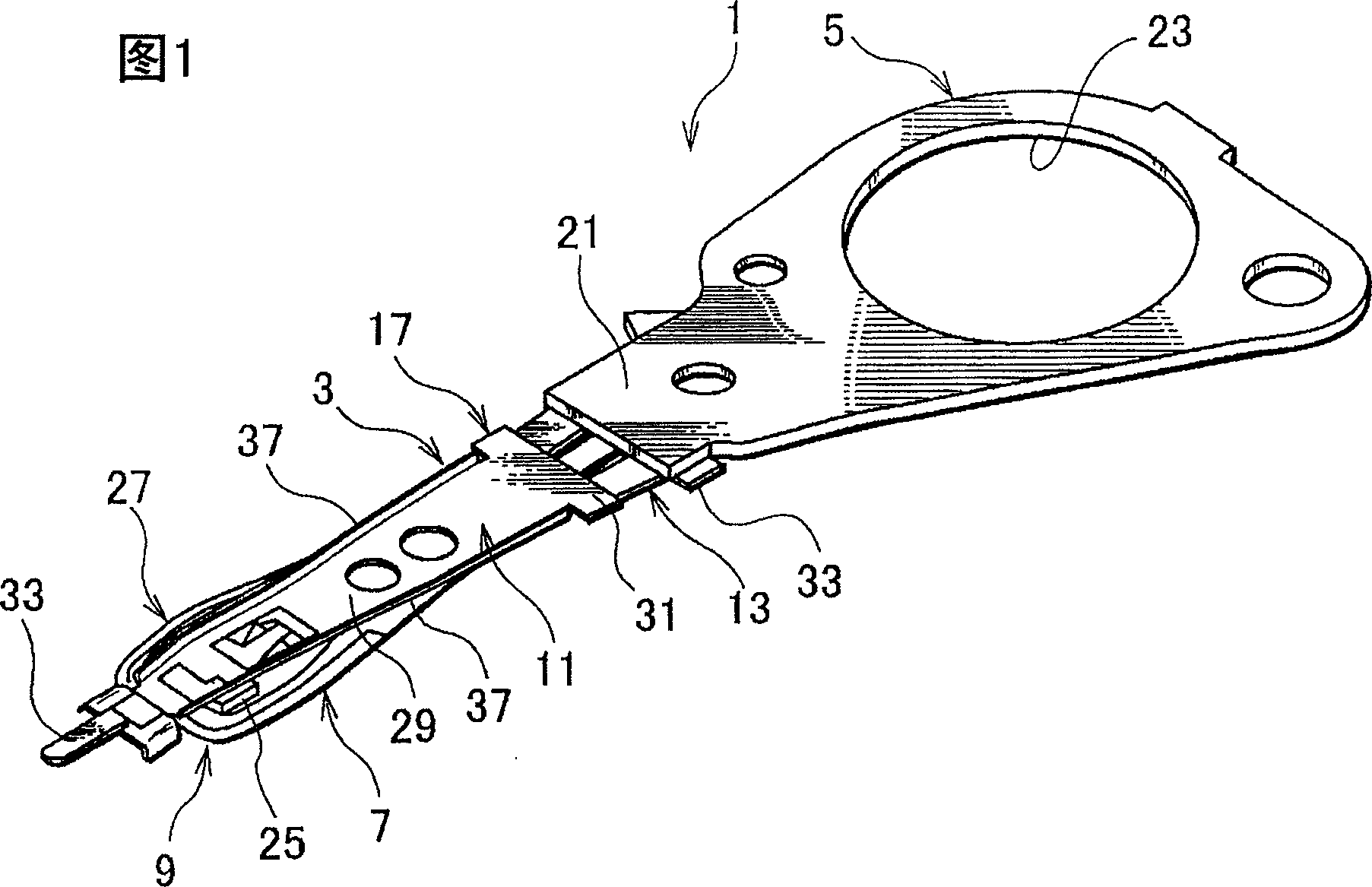
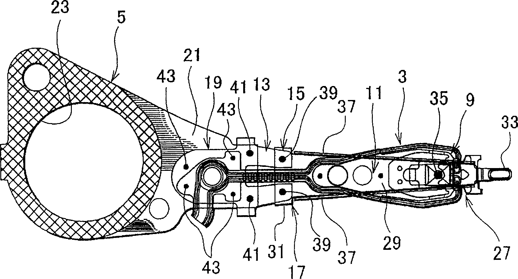
[0047] Figure 1 and figure 2 Showing a head suspension according to a first embodiment of the present invention, FIG. 1 is a perspective view, figure 2 is a top view.

[0048] The head suspension 1 shown in Figs. 1 and 2 is for a 1-inch size, for example. The head suspension has a load beam 3 , an arm 5 and a flexure 7 .

[0049] The load beam 3 applies a load to the magnetic head 9 . The magnetic head 9 is arranged at the front end of the load beam 3 to read data from the magnetic disk and write data to the magnetic disk. The load beam 3 includes a beam 11 serving as a rigid member and a hinge 13 serving as an elastic member.

[0050] The hinge 13 is prepared to be separated from the beam 11 . The first end 15 of the hinge 13 is fixed and supported on the base end 17 of the beam 11 , and the second end 19 of the hinge 13 is fixed and supported on the arm 5 .

[0051] The arm 5 comprises an integrated base plate 21 serving as a base for supporting the second end 19 of ...


PUM

PropertyMeasurementUnit
thicknessaaaaaaaaaa
lengthaaaaaaaaaa
thicknessaaaaaaaaaa

Abstract

A head suspension for a disk drive is capable of improving shock property of the hard disk drive while miniaturizing the hard disk drive. A head suspension has a base plate to be attached to a carriage and turned around a spindle of the carriage, a load beam which includes a beam and a hinge, a base end of the beam being supported to the base plate through the hinge and which applies a load onto a head for writing and reading data to and from a disk at a front end side thereof, and a flexure which connects the head to writing and reading wires and supports the head and which is attached to the load beam, where the hinge is set to be relatively thicker than the beam so that the load beam is made thin and the load is increased.

Description

technical field [0001] The present invention relates to a head suspension of a hard disk drive integrated in an information processing unit such as a personal computer. Background technique [0002] A head suspension of a hard disk drive includes a load beam, a head supported by the load beam, and a slider attached to the head. The head suspension has a shock characteristic that determines the lift of the slider from the hard disk surface when a shock is applied. The shock characteristics of the head suspension depend on the weight of the load beam. [0003] For example, the first head suspension has a load beam with a thickness (t) of 51 μm and a length (1L) of 7 mm, and the gram load applied to the head by the load beam is 2.5 gf, and the second head suspension has a thickness (t) A load beam of 30 μm, length (1L) of 5.5 mm, and a gram load of 2.5 gf. If a shock lasting 1 Msec is applied to the head suspension, the slider of the first head suspension lifts up with an ac...

Claims


Application Information

Patent Timeline
Patent Type & Authority Applications(China)
IPC IPC(8): G11B21/21
CPCG11B5/4833
Inventor 绵谷荣二半谷正夫唐泽巧
Owner NHK SPRING CO LTD
Learn More