
Optical device, light irradiation apparatus and light irradiation method

An optical device and optical radiation technology, which is applied in the field of optical radiation devices and optical radiation, can solve problems such as difficult to predict the change of beam state in advance, and achieve the effect of improving the inhomogeneity of radiation energy and improving optical performance

Inactive Publication Date: 2006-10-18
SONY CORP
View PDF1 Cites 0 Cited by
  • Summary
  • Abstract
  • Description
  • Claims
  • Application Information

AI Technical Summary

Problems solved by technology

In this way, it is also difficult to predict the change of the beam state in advance and prepare a replacement homogenizer

Method used


Image

  • Optical device, light irradiation apparatus and light irradiation method
  • Optical device, light irradiation apparatus and light irradiation method
  • Optical device, light irradiation apparatus and light irradiation method

Examples


specific Embodiment

[0056] Specific examples of the present invention will be described below. attached Figure 6A It shows that using the optical radiation method using the optical device in the above-mentioned embodiment, by means of a wavelength of 390nm, a pulse width of 3 picoseconds and a radiation energy of 0.13mJ / cm 2 The results obtained by the processing of laser radiation with a thickness of 500nm aluminum film to form holes in the aluminum film. It can be seen from the results that although the actual radiation energy can be considered to be about 0.12mJ / cm after considering the loss of laser energy passing through the optical component 2 2 , but ideal processing can be obtained without unprocessed film, and almost no dust generated by processing can be seen.

[0057] On the other hand, when the conventional optical radiation method without using the optical device of the present invention is carried out with a wavelength of 390 nm, a pulse width of 3 picoseconds, and a radiation en...


PUM

PropertyMeasurementUnit
refractive indexaaaaaaaaaa

Abstract

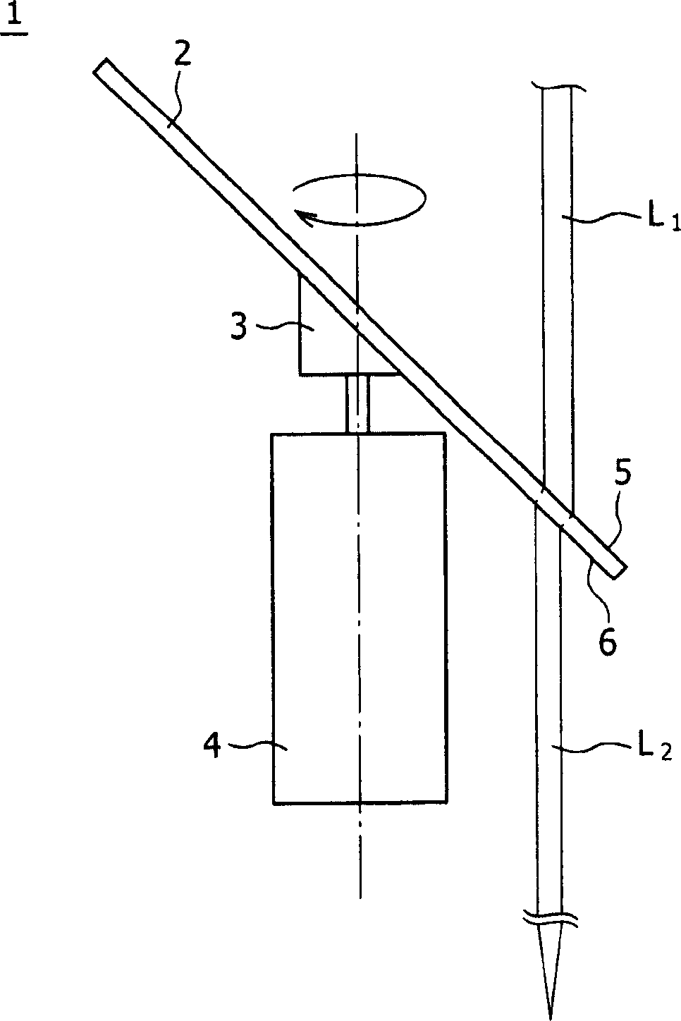
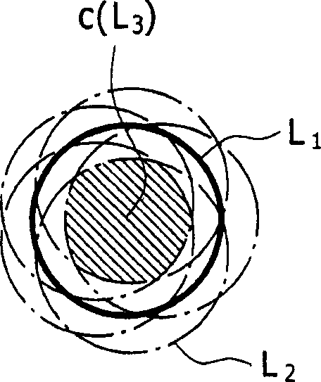
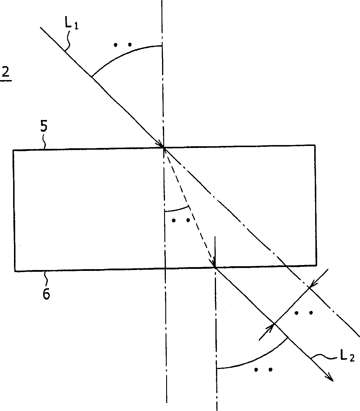
An optical device is provided. The optical device including an optical member having a first main surface and a second main surface, which respectively serve as an entrance surface and an exit surface for light from a directional light source, and made of a material having a refractive index greater than 1; and a support member at least including swing means for the optical member, wherein the first and second main surfaces of the optical member swingable by the support member are able to be inclined with respect to an optical path of the light from the directional light source.

Description

technical field [0001] The present invention relates to an optical device, wherein the device is used to limit the light path of light emitted from a directional light source, and also relates to a light radiation device and a light radiation method having the optical device. Background technique [0002] In the technical field of directional light such as lasers and LEDs (Light Emitting Diodes), it is necessary to form ideal light by selecting the spot shape, spot diameter, light quantity, energy distribution, etc. of directional light emitted from the above light sources. [0003] For example, lasers are widely used in various processes, including laser repair, laser annealing, laser cleaning, and laser etching, for photomasks in the manufacture of semiconductor devices, liquid crystal displays, or organic electroluminescent displays. It is also used in the wiring inspection of TFT circuit boards. However, when a laser beam is emitted from a light source, the quality of t...

Claims


Application Information

Patent Timeline
Patent Type & Authority Applications(China)
IPC IPC(8): G02B27/09G02B26/02H01L21/00H01S3/00
CPCB23K26/03B23K26/073G02B27/0933G02B27/095B23K26/066B23K2101/40
Inventor 川部英雄名田直司舆石亮
Owner SONY CORP
Learn More