Protective part for the leading edge of a blade

一种保护件、前缘的技术,应用在叶片的支承元件、泵元件、用于弹性流体的泵送装置的部件等方向,能够解决保护件重量大等问题

Active Publication Date: 2006-10-18
SN DETUDE & DE CONSTR DE MOTEURS DAVIATION (S N E C M A)
View PDF0 Cites 30 Cited by
  • Summary
  • Abstract
  • Description
  • Claims
  • Application Information

AI Technical Summary

Problems solved by technology

But found that such a protective piece is too heavy

Method used


Image

  • Protective part for the leading edge of a blade
  • Protective part for the leading edge of a blade

Examples


Embodiment Construction

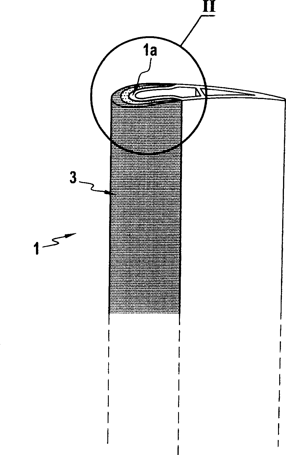
[0016] figure 1 and figure 2 The airfoil portion of a turbine blade 1 is shown, the leading edge 1a of the blade 1 being covered with a protective element 3 according to the invention.

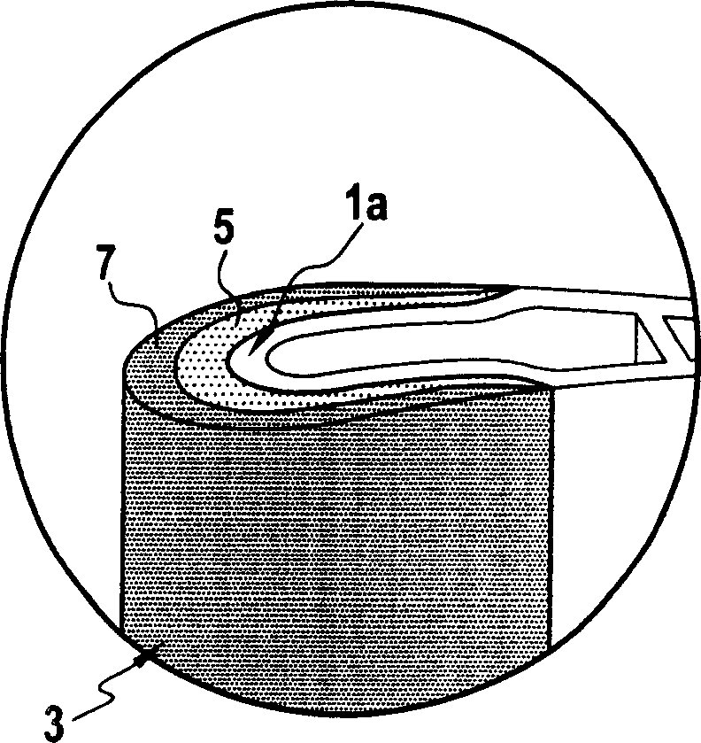
[0017] The cross-section of the protective element 3 is substantially U-shaped, enabling it to be placed across the leading edge 1 a of the blade 1 . Part 3 consists of two layers, an inner layer 5 and an outer layer 7 . The outer layer 7 is made of aluminum alloy reinforced with SiC particles, while the inner layer 5 is the same grade of aluminum alloy but not reinforced with SiC. For aerospace applications, the 7000 series aluminum alloys are preferred.

[0018] Of course, the protective part can have more than two layers, and the content of SiC particles in each layer gradually increases from the inside to the outside. Thus, in an embodiment not shown, the protector has four layers C 1 、C 2 、C 3 、C 4 , inner layer C 1 The content of SiC in is zero, C 2 The content in is about 10%...


PUM


Abstract

A protective element (3) consisting of at least two layers, an inner layer (5) and an outer layer (7), the outer layer (7) of which is made of an aluminum alloy reinforced with SiC particles in said alloy The content range is 15% to 40% by weight, and the inner layer (5) is made of aluminum alloy, which can be reinforced with SiC particles at will, and the content of SiC particles in each layer gradually increases from the inner layer to the outer layer. Said part is intended to protect the leading edge (1a) of a blade, in particular a moving blade and a stationary blade of a turbine, a helicopter phase rotor blade or a propeller blade.

Description

technical field [0001] The invention relates, for example, to a protection for the leading edge of a turbine blade, a propeller blade or a helicopter rotor blade. Background technique [0002] In the field of aviation, and more specifically in the field of turbojet engines for aircraft, weight reduction of turbojet engine components is always the first thing to pay attention to. [0003] Therefore, blades made of organic matrix composites (such as those based on cyanate esters, bismaleimide, or epoxy resins) have been developed for fans or stators of turbojet engines, so that the blades Lighter than metal blades. [0004] However, with such blades, the leading edge needs to be protected against wear and possible impact by means of protective elements fitted to the leading edge. [0005] So far, the protective parts that have been made are made of TA6V titanium alloy. This approach is technically feasible because of the alloy's good wear and impact resistance. However, it...

Claims


Application Information

Patent Timeline
Patent Type & Authority Applications(China)
IPC IPC(8): C22C21/00F01D5/28
CPCB23P15/04F01D5/147F01D5/28F05D2300/702F05D2300/2261F05D2300/173F04D29/324F05D2240/303Y10T428/30Y10T428/12764Y10T428/12458Y10T428/31678Y02T50/60
Inventor 杰魁斯·伯纳德克劳德·芒斯伊莎贝勒·帕斯勒比蒂埃里·托马斯
Owner SN DETUDE & DE CONSTR DE MOTEURS DAVIATION (S N E C M A)
Why Eureka
Try Eureka