
After-current circuit breaker operation mechanism

A technology of residual current and operating mechanism, applied in the field of residual current circuit breakers, can solve problems such as complex structure, and achieve the effects of labor-saving operation, guaranteed structural characteristics, and simplified components

Active Publication Date: 2014-05-21
SASSIN INT ELECTRIC SHANGHAI CO LTD
View PDF6 Cites 9 Cited by
  • Summary
  • Abstract
  • Description
  • Claims
  • Application Information

AI Technical Summary

Problems solved by technology

[0004] In view of the above-mentioned shortcomings of the prior art, the object of the present invention is to provide an operating mechanism for a residual current circuit breaker, which is used to solve the need for free tripping in the prior art with the help of external force, and the structure of the free tripping function is complex and does not require The problem of residual current disconnection for large currents

Method used


Image

  • After-current circuit breaker operation mechanism
  • After-current circuit breaker operation mechanism
  • After-current circuit breaker operation mechanism

Examples


Embodiment Construction

[0040] The implementation of the present invention will be illustrated by specific specific examples below, and those skilled in the art can easily understand other advantages and effects of the present invention from the contents disclosed in this specification.

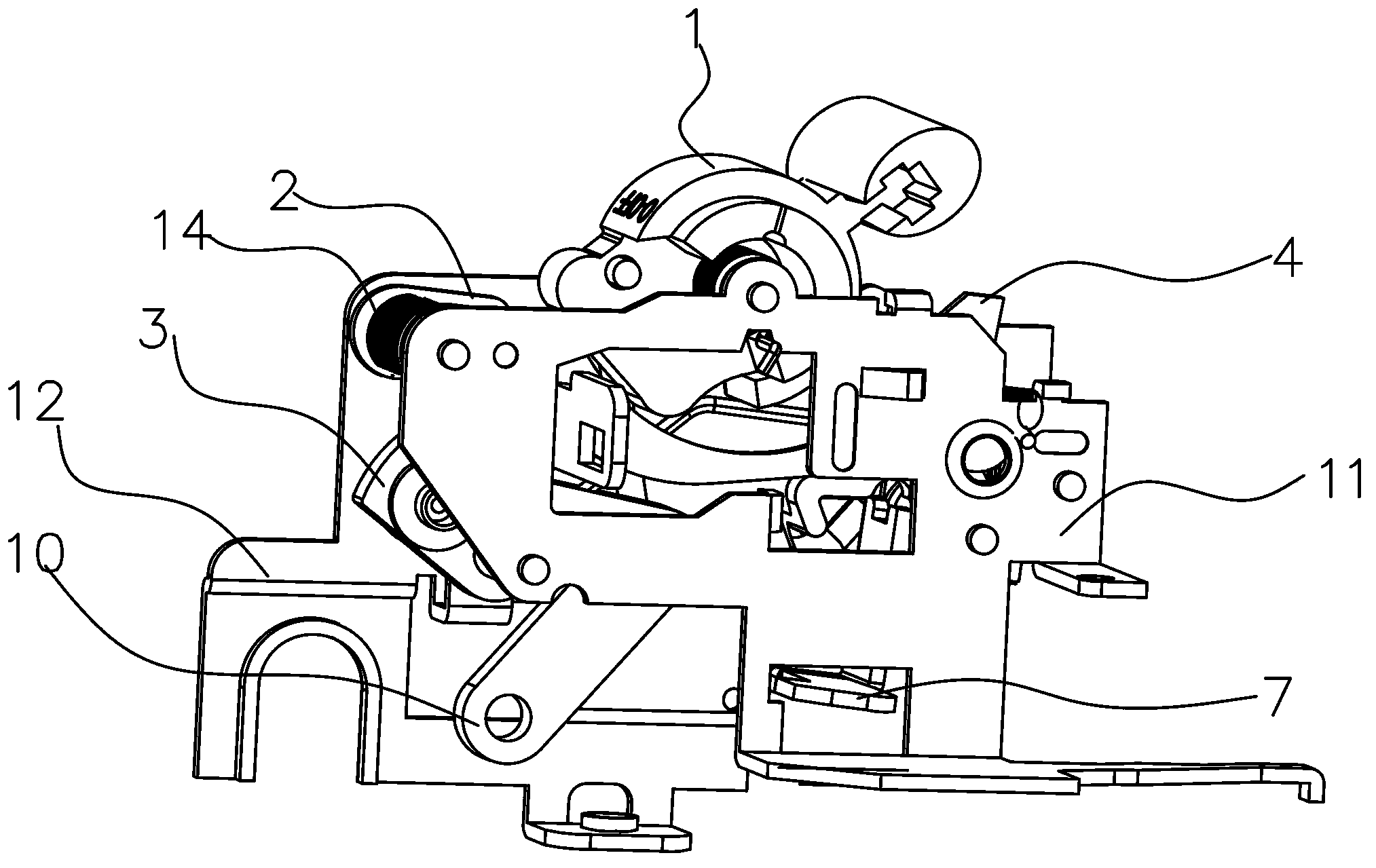
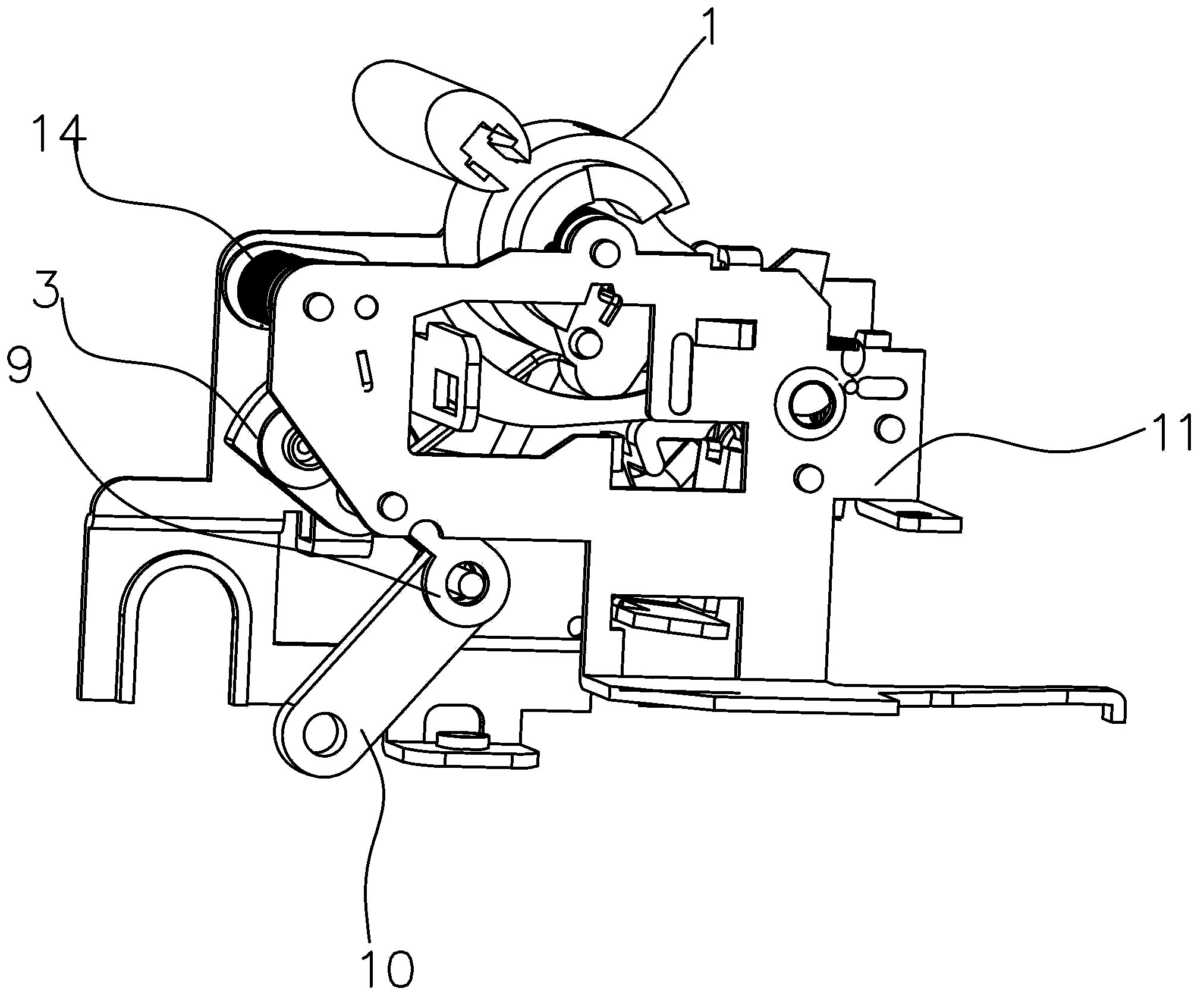
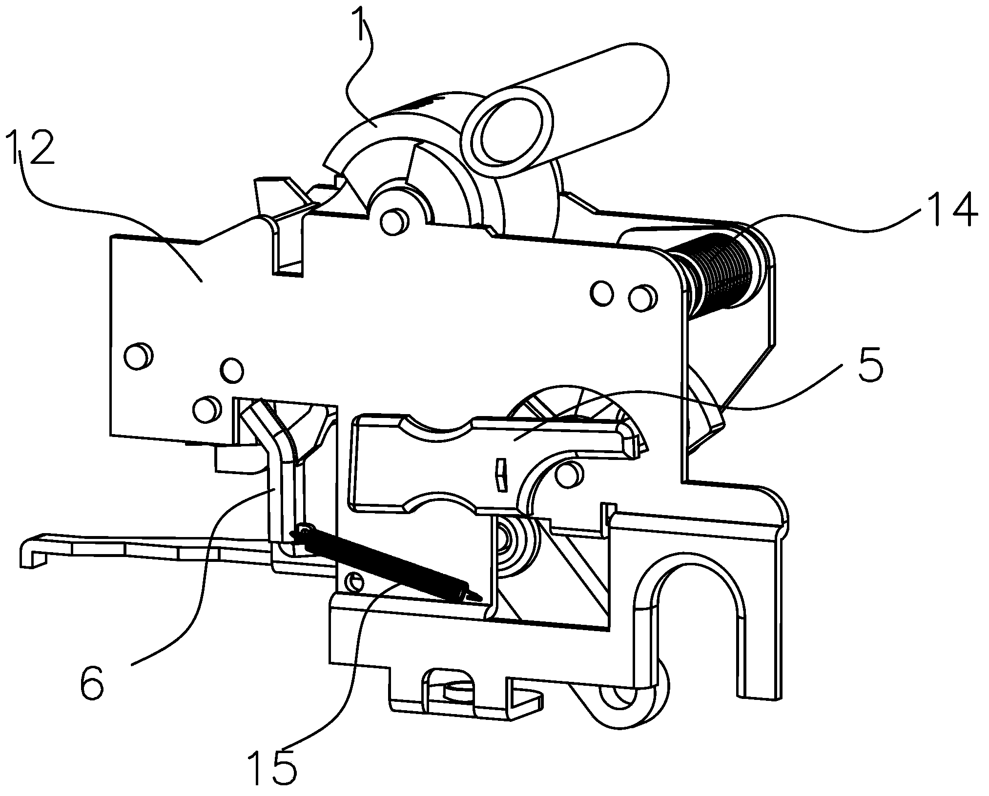
[0041] see Figure 1 to Figure 5 . It should be noted that the structures, proportions, sizes, etc. shown in the drawings attached to this specification are only used to match the content disclosed in the specification, for those who are familiar with this technology to understand and read, and are not used to limit the implementation of the present invention. Limiting conditions, so there is no technical substantive meaning, any modification of structure, change of proportional relationship or adjustment of size, without affecting the effect and purpose of the present invention, should still fall within the scope of the present invention. The disclosed technical content must be within the scope covered. At the sa...


PUM


Abstract

The invention provides an after-current circuit breaker operation mechanism which comprises a handle and a transmission mechanism which are arranged in a rotating mode, a tripping fastening assembly, a releasing piece and a free releasing mechanism. The transmission mechanism comprises a first connection rod connected with a handle and a second connection rod in pivoting connection with the first connection rod. The second connection rod is in transmission connection with a movable contact. The tripping fastening assembly comprises a tripping fastening piece, a locking fastening piece, a tripping fastening spring and a locking fastening spring. The releasing piece drives the locking fastening piece to move to enable the tripping fastening piece to be separated from the locking fastening piece. The free releasing mechanism enables the movable contact to move when the handle does not rotate. The free releasing mechanism comprises a cam arranged in a rotating mode and a third connection rod, a protruding portion of the cam contacts the tripping fastening piece in an abutting mode, one end of the third connection rod is in pivoting connection with the cam, and the other end of the third connection rod is in pivoting connection with the connection position of the second connection rod and the first connection rod. When the stripping fastening piece is separated from the locking fastening piece, the cam drives the tripping fastening piece to rotate to drive the third connection rod to drive the second connection rod to move to drive the movable contact to move. The mechanism is simple in structure and capable of achieving a free releasing function without the aid of external force.

Description

technical field [0001] The invention relates to a residual current circuit breaker, in particular to an operating mechanism of the residual current circuit breaker. Background technique [0002] As we all know, in the terminal power distribution of low-voltage power distribution system, residual current circuit breakers need to be installed to protect people from direct contact and electrical fire. In practical application, the normal connection and disconnection current of a large number of residual current circuit breakers can only reach 40A, and very few parts can reach 63A. When the rated current of the use place exceeds 63A, the use of residual current circuit breakers will encounter problems difficulty. In the actual use of residual current circuit breakers, some do not have the free trip function, and some circuit breakers have the free trip function, but the circuit breaker with the free trip function needs the help of external force to realize the free trip functio...

Claims


Application Information

Patent Timeline
Patent Type & Authority Applications(China)
IPC IPC(8): H01H71/10H01H71/50
Inventor 郑永刚苏邯林孙利亚李阳张国明
Owner SASSIN INT ELECTRIC SHANGHAI CO LTD
Learn More