
Impact tool

A technology of impact tools and tools, which is applied in the field of impact tools, can solve problems such as loud noise, and achieve the effect of reducing noise and preventing cracking

Inactive Publication Date: 2006-10-18
HITACHI KOKI CO LTD
View PDF2 Cites 4 Cited by
  • Summary
  • Abstract
  • Description
  • Claims
  • Application Information

AI Technical Summary

Problems solved by technology

[0009] In addition, in the work using such an impact tool, since the hammer 8 makes longitudinal motions while rotating, these motions serve as a source of vibration, passing through the anvil 3, the tip tool 4, and the screw 11, making the object to be fastened The wood 12 vibrates axially, resulting in greater noise

Method used


Image

  • Impact tool
  • Impact tool
  • Impact tool

Examples


Embodiment 1

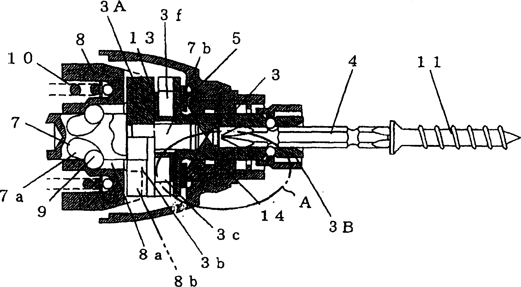
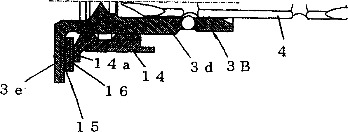
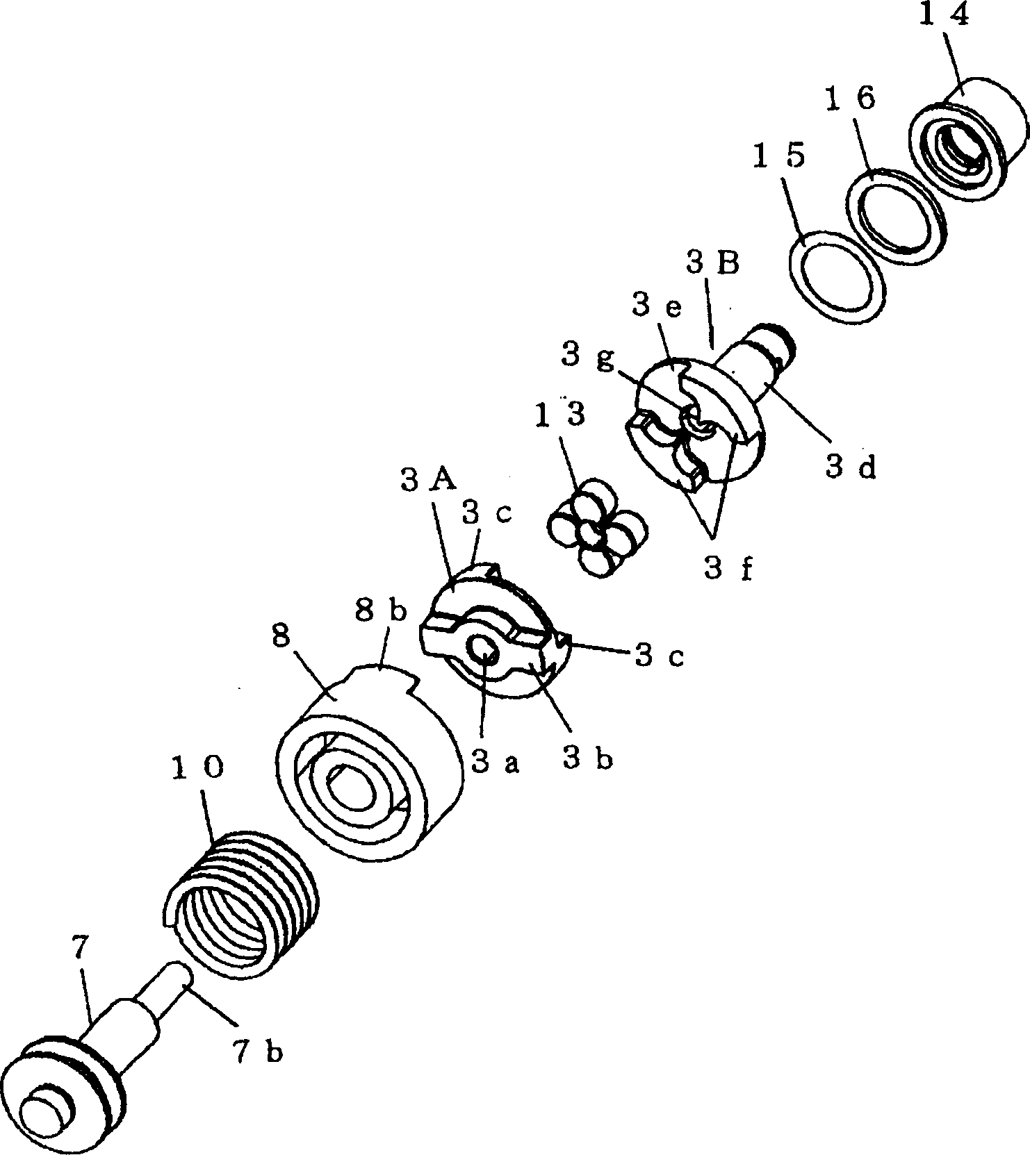
[0040] figure 1 To show a longitudinal sectional view of the rotary impact mechanism portion of the impact tool according to the present embodiment, figure 2 is a view showing details of part A on an enlarged scale, image 3 and 4 To show an exploded isometric view of the rotary impact mechanism portion of the impact tool, Figure 5 To show a side view of the anvil, and, Figure 6 along Figure 5 Sectional view taken along midline B-B.

[0041] The impact tool according to the present embodiment is a cordless, portable tool having a battery pack as a power source and an electric motor as a drive source, and has the same configuration as in the Figure 12 The construction of the conventional impact tool shown in is the same. Therefore, omitting the pair with Figure 12 Repeated explanations showing configurations that are identical in configuration give only explanations for configurations unique to the present invention.

[0042] The impact tool according to the present ...

Embodiment 2

[0067] Below, combine Figure 10 and 11 describe Embodiment 2 of the present invention. in addition, Figure 10 To show a longitudinal sectional view of the rotary impact mechanism portion of the impact tool according to the present embodiment, FIG. 11 is a view along the Figure 10 Enlarged cross-sectional views taken along midline C-C, in these figures with figure 1 and 2 Components that are the same as those in are denoted by the same reference numerals as the latter.

[0068] The impact tool according to the present embodiment has a feature that the buffer mechanism is provided on the tip tool 4 . Here, the buffer mechanism realizes the buffer function in the direction of rotation and in the axial direction, and directly transmits the set value or greater torque in the same manner as in Embodiment 1. The buffer mechanism specifically includes: split parts 4A, 4B, by The tip tool 4 is provided split in half in the axial direction; and a rubber damper 17 is interposed ...


PUM


Abstract

An impact tool comprising a motor, a hammer 8 that is rotated and axially moved by a drive force of the motor, an anvil 3 that repeats engagement / disengagement from the hammer 8 accompanying rotation and axial movements of the hammer 8, and a tip tool 4 mounted to the anvil 3, the anvil 3 comprising a first split piece 3 A, which includes pawls 3 c (first concave-convex part) on an opposite side to the hammer and repeats engagement / disengagement from the hammer 8, a second split piece 3 B, which includes pawls 3 f (second concave-convex part) engageable with the pawls (first concave-convex part) 3 c of the first split piece 3 A in a direction of rotation, and to which the tip tool 4 is mounted, and a rubber damper (elastic body) 13 interposed between the first and second split pieces 3 A, 3 B to prevent direct contact between the pawls (first concave-convex part) 3 c and the pawls (second concave-convex part) 3 f in the direction of rotation and in an axial direction.

Description

technical field [0001] The present invention relates to the generation of rotational impact force to carry out the required work such as screw fastening etc. [0002] Impact tools, and more particularly, relate to impact tools that achieve noise reduction. Background technique [0003] An impact tool with a power tool configuration uses a motor as a driving source to generate a rotating impact force to rotate the tip tool, thereby intermittently applying impact force to it for operations such as screw fastening, and since the impact tool has less reaction , High fastening and installation capabilities, etc., are currently widely used. However, since such an impact tool includes a rotary impact mechanism to generate a rotary impact force, the noise during operation is relatively large, causing noise problems. [0004] Figure 12 A longitudinal cross-section of a common impact tool in conventional use is shown. [0005] exist Figure 12 The conventional impact tool shown in...

Claims


Application Information

Patent Timeline
Patent Type & Authority Applications(China)
IPC IPC(8): B25D16/00B23B45/16B25B21/02B25D17/24
CPCB25B21/02B25B21/026B25F5/006
Inventor 村上卓宏上村淳一大森和博大津新喜稻川裕人
Owner HITACHI KOKI CO LTD
Learn More