Linear slide fastener
A zipper and linear technology, applied in clothing, printing, and information-carrying cards, etc., can solve the problems of rising costs and waste of resources, and achieve the effects of saving resources and reducing the size of reinforcement
- Summary
- Abstract
- Description
- Claims
- Application Information
AI Technical Summary
Problems solved by technology
Method used
Image

Examples
no. 1 example
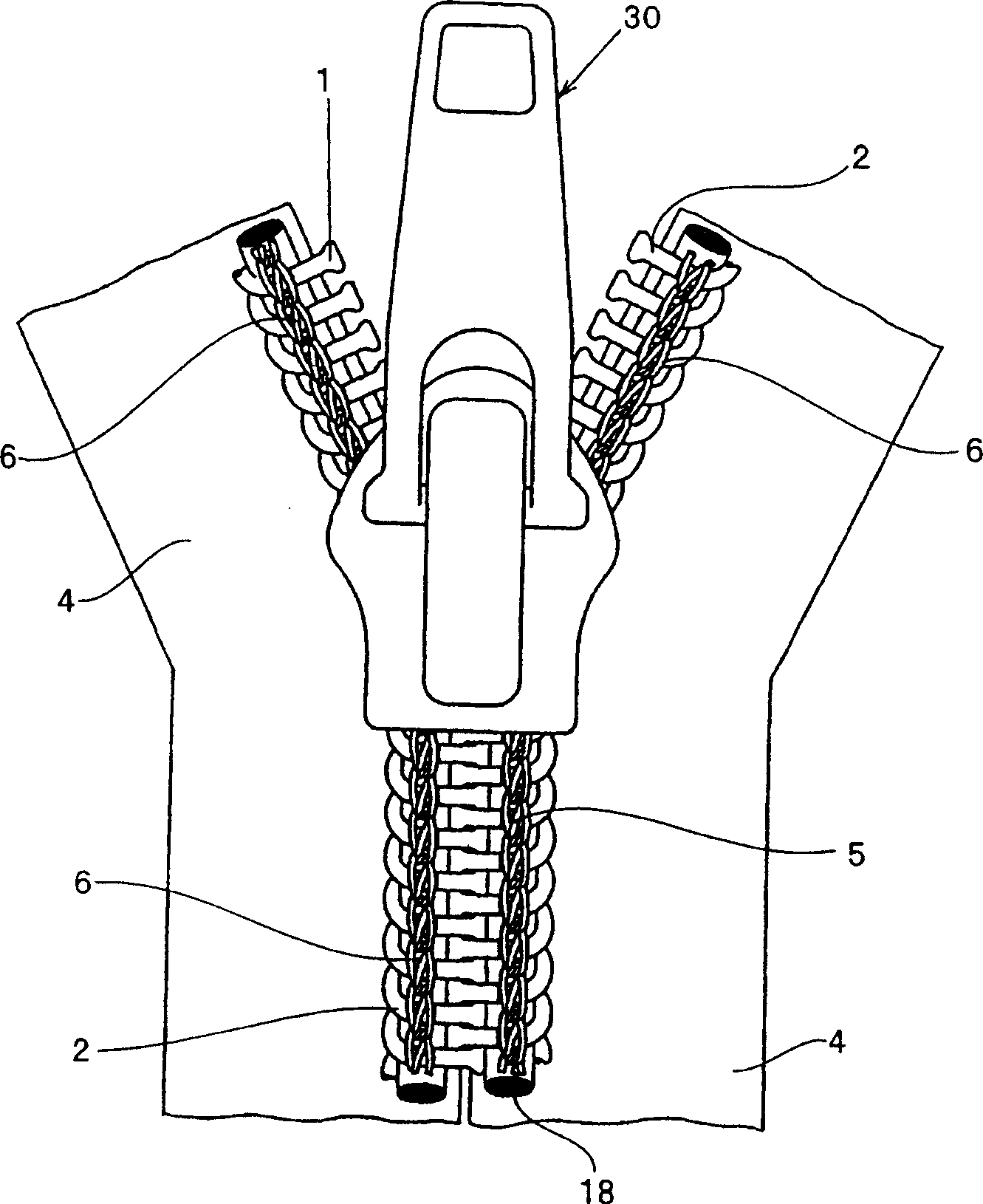
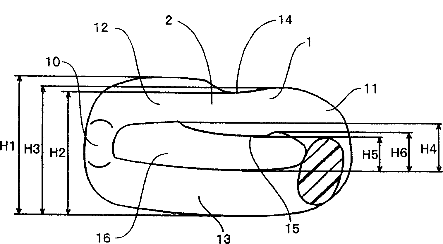
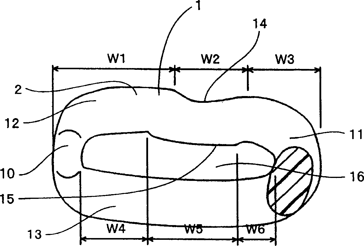
[0042] If the linear zipper of the present invention is explained, Figures 1 to 7 In the linear slide fastener of the first embodiment shown, its linear slide fastener member 1 is formed by winding polyamide or polyester monofilament into a coil shape. In the linear zip component 1, as in Figures 2 to 6 As shown, a coupling head 10 is formed at one end and a reverse portion 11 is formed at the other end and the two parts are connected with an upper leg 12 and a lower leg 13 to form a coiled zipper member 2 . The coiled zipper member 2 is sewn to the sides of the zipper tape 4 with sewing thread 6 , for example, double loop sewing using two needles and three threads with a center line 18 passing through the inside of the coiled zipper member 2 .
[0043] In the coiled fastener member 2, such as figure 2 As shown in , when the height between the top surface of the upper leg 12 and the bottom surface of the lower leg 13 on the side of the coupling head 10 is assumed to be H1...
no. 2 example
[0052] according to Figure 8 The shown linear slide fastener of the second embodiment of the present invention is a concealed type slide fastener having folded portions 22 on the sides of the fastener tape 4, wherein the left and right folded portions 22 abut against each other and have the same design as the above-mentioned coiled fastener member 2. The conditioned upper leg portion 12 is sewn and secured by using the sewing thread 6 as a double loop stitching of the securing thread 5 passing through the recess 14 . In this case, the recess 14 is formed in the leg placed on the outside. This hidden type zipper has the same setting conditions as the above example so that the fixing wire 5 is accommodated in the recess 14 formed in the upper leg 12 so as to be prevented from moving and slipping from the coupling head 10 side. The reverse portion 11 at one end of the coiled zipper member 2 can be formed in a small size so that the entirety of the coiled zipper member 2 can be ...
no. 3 example
[0054] according to Figure 9 The shown linear slide fastener of the third embodiment of the present invention is a linear slide fastener produced by sewing and fixing the zigzag fastener member 3 on the side of the fastener tape 4 using the sewing thread 6 as the double loop sewing of the fixing thread 5 . The zigzag zipper member 2 is provided with the same various setting conditions as those of the above examples and the upper leg portion 12 on the coupling head 10 side is formed with a steep slope and the upper leg portion 12 on the reverse portion 11 side is formed into a steep slope. Form a gentle slope. The center line 18 is inserted between the upper leg 12 and the lower leg 13 of this zigzag zipper member 3 and the recess 14 formed in the upper leg 12 is made by using the sewing thread 6 of the double loop sewing as the fixing thread 5 be fixed.
[0055] The linear zipper member 1 of this embodiment is set under the same setting conditions as the aforementioned cond...
PUM
 Abstract
Description
Claims
Application Information
 - R&D
- Intellectual Property
- Life Sciences
- Materials
- Tech Scout
- Unparalleled Data Quality
- Higher Quality Content
- 60% Fewer Hallucinations
Browse by: Latest US Patents, China's latest patents, Technical Efficacy Thesaurus, Application Domain, Technology Topic, Popular Technical Reports.
© 2025 PatSnap. All rights reserved.Legal|Privacy policy|Modern Slavery Act Transparency Statement|Sitemap|About US| Contact US: help@patsnap.com