Oil pump

A technology of oil pumps and shallow tanks, applied in the field of gear pumps, can solve the problems of bubble collapse (breakage, erosion, bubble collapse, etc.), and achieve the effects of improving durability, easy replenishment, and preventing erosion

Active Publication Date: 2006-09-27
YAMADA SEISAKUSHO KK
View PDF0 Cites 10 Cited by
  • Summary
  • Abstract
  • Description
  • Claims
  • Application Information

AI Technical Summary

Problems solved by technology

[0007] Furthermore, since the small port disclosed in Patent Document 1 directly intersects the interdental chamber moving toward the discharge port side, a pressure fluctuation occurs at the small port at the moment of communication with the interdental chamber, which may cause The air bubbles trapped at the bottom of the teeth of the inner rotor are directly collapsed (ruptured). At this time, the small port cannot fully cope with hydraulic pressure fluctuations, and there is a possibility of an erosion phenomenon in which the air bubbles generated due to cavitation are instantly collapsed (broken).
[0008] Due to the erosion phenomenon, impact scars caused by the generation and collapse (rupture) of a large number of air bubbles in an instant will occur in the inner rotor, outer rotor, and casing, which will adversely affect the pump efficiency and even make it difficult to maintain the specified pump. performance
That is, although the fluid in the interdental chamber that transfers the fluid to the discharge port can be prevented from suddenly flowing into the discharge port, erosion (corrosion) may still occur because the erosion phenomenon cannot be prevented.

Method used


Image

  • Oil pump
  • Oil pump
  • Oil pump

Examples


Embodiment Construction

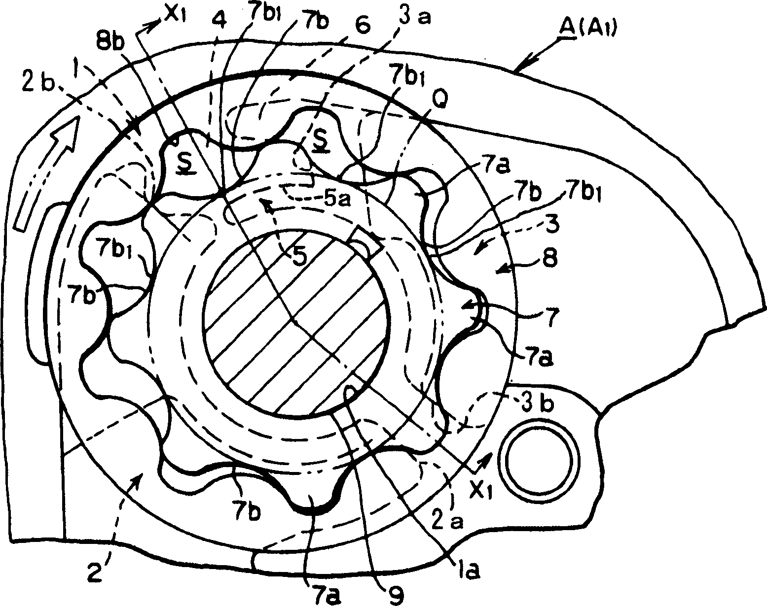
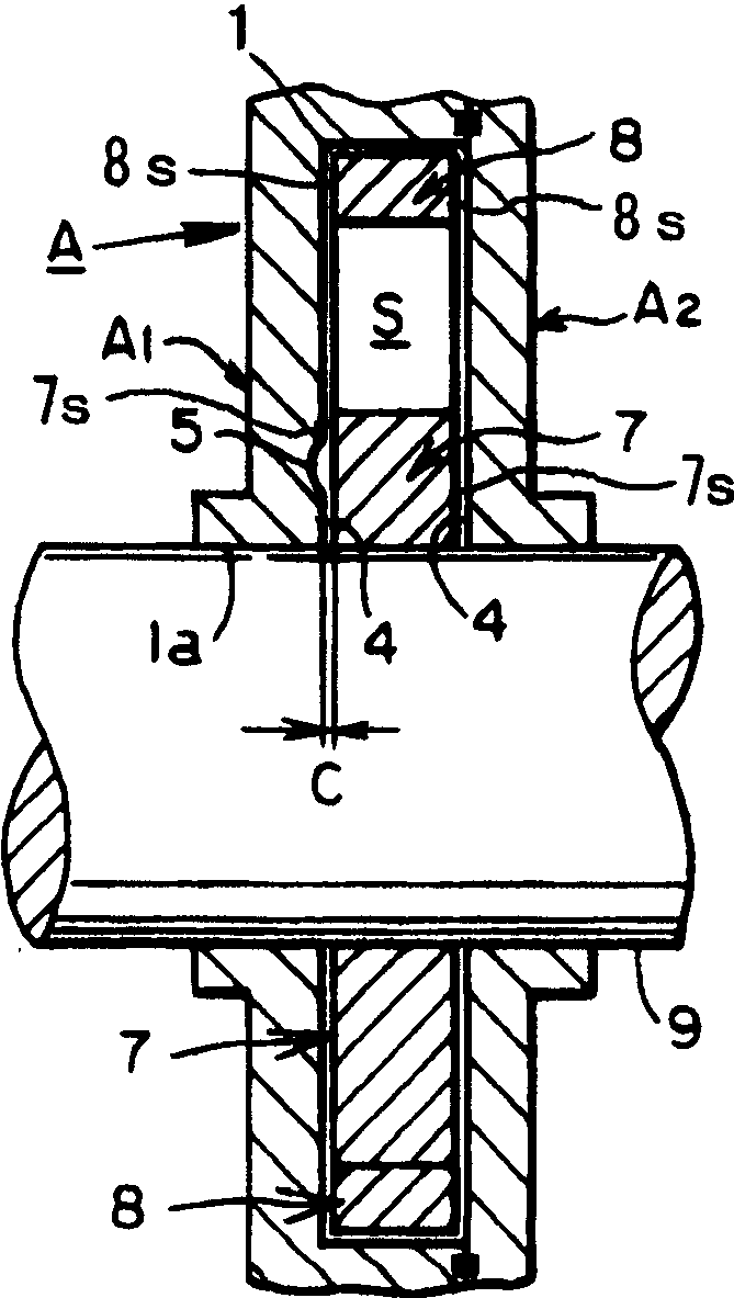
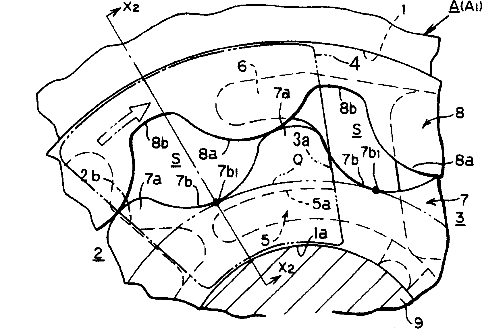
[0027] Embodiments of the present invention will be described below based on the drawings. Oil pump of the present invention, as Figure 1A As shown, in the rotor chamber 1 formed in the casing A, the inner rotor 7 and the outer rotor 8 having a trochoid tooth shape are housed. Fig. 2 is the housing body part A of the housing A 1 The top view of the main part, in the aforementioned rotor chamber 1, such as Figure 2A As shown, a suction port 2 and a discharge port 3 are formed on its substantially outer periphery along its circumferential direction. The suction port 2 and the discharge port 3 are formed asymmetrically in the rotor chamber 1 . Alternatively, the suction port 2 and the discharge port 3 may be bilaterally symmetrical.

[0028] Such as Figure 1A As shown, the number of teeth of the inner rotor 7 is one less than that of the outer rotor 8, and there is a relationship that when the inner rotor 7 makes one revolution, the outer rotor 8 rotates slower than that. ...


PUM


Abstract

The present invention provides an oil pump in which eroding of the inside of the pump due to cavitation and erosion is prevented by minimizing the pressure change in a fluid when inter-tooth spaces formed by an inner rotor and an outer rotor transport the fluid from the intake port to the discharge port. The oil pump comprises: an inner rotor; an outer rotor; an intake port; a discharge port; a transfer side partition part formed between a terminal end of the intake port and a leading end of the discharge port; and a shallow groove which is formed in the transfer side partition part, and which communicates with the discharge port but does not communicate with the intake port. The shallow groove does not intersect with the cell on the transfer side partition part, and is positioned farther inward than the circular locus of the gear bottom parts of the inner rotor. The shallow groove communicates with the cell through a side clearance between the transfer side partition part and the rotor side surfaces of the inner rotor and the outer rotor.

Description

technical field [0001] The present invention relates to an internal meshing type gear pump in which the pressure fluctuation of the fluid enclosed in the inter-tooth space is suppressed while the fluid is transferred from the suction port to the discharge port in each inter-tooth space constituted by an inner rotor and an outer rotor. Minimize and soften it, prevent corrosion inside the pump caused by cavitation and erosion, and its structure is very simple. Background technique [0002] There are widely available pumps of the type in which the interdental chamber is filled with fluid from the suction port in the interdental chamber formed by the outer rotor and the inner rotor having a trochoidal tooth shape, and the stroke is reduced from the maximum volume state to the volume The transition side discharges fluid toward the discharge port. In such a pump, the volume of the interdental chamber gradually changes due to the structural reason of the subcycloidal tooth profile...

Claims


Application Information

Patent Timeline
Patent Type & Authority Applications(China)
IPC IPC(8): F04C2/10
CPCF04C15/0049F04C15/06F04C2250/102
Inventor 远坂和郎小野靖典西冈专太郎笠原昌广金子敦史
Owner YAMADA SEISAKUSHO KK
Why Eureka
Try Eureka