Control valve for a fuel injector that contains a pressure intensifier

A technology of fuel injectors and converters, which is applied in the direction of fuel injection pumps, fuel injection devices, charging systems, etc., which can solve the problem of precise and fast closing movement of valve pistons, which cannot achieve precise and fast closing movements. Large spring force , large structural space and other issues, to achieve the effect of small sealing diameter, simple manufacturing, and reduced leakage

Inactive Publication Date: 2006-09-13
ROBERT BOSCH GMBH
View PDF0 Cites 10 Cited by
  • Summary
  • Abstract
  • Description
  • Claims
  • Application Information

AI Technical Summary

Problems solved by technology

This in turn leads to the fact that a precise and rapid closing movement of the valve piston is difficult to achieve with this solution, since the high spring force required to bring about a precise and rapid closing movement cannot be realized in the injector construction chamber
The large stroke of the valve piston designed as a slide valve requires a large installation space in order to achieve high spring forces

Method used


Image

  • Control valve for a fuel injector that contains a pressure intensifier
  • Control valve for a fuel injector that contains a pressure intensifier
  • Control valve for a fuel injector that contains a pressure intensifier

Examples


Embodiment Construction

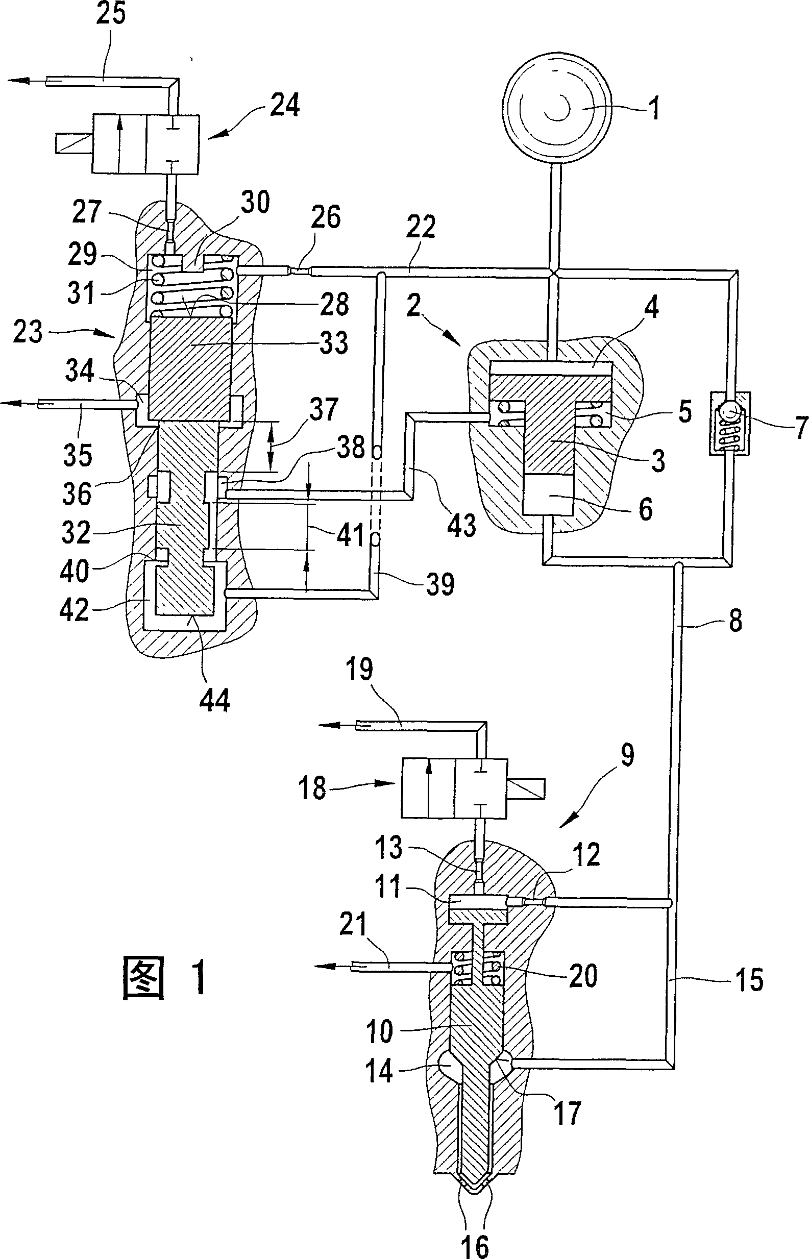
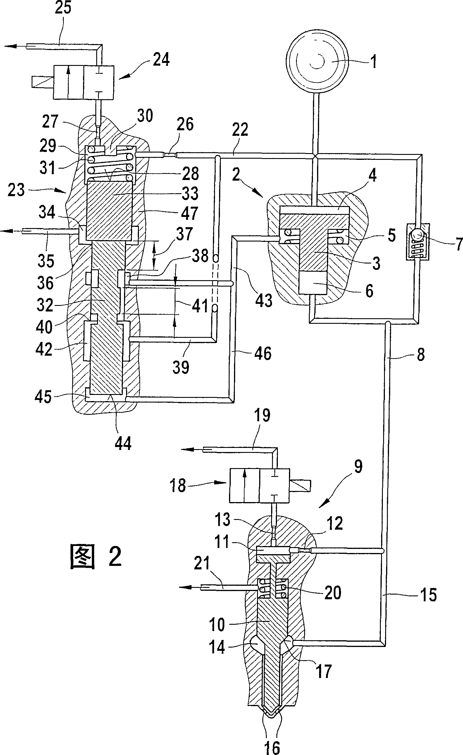
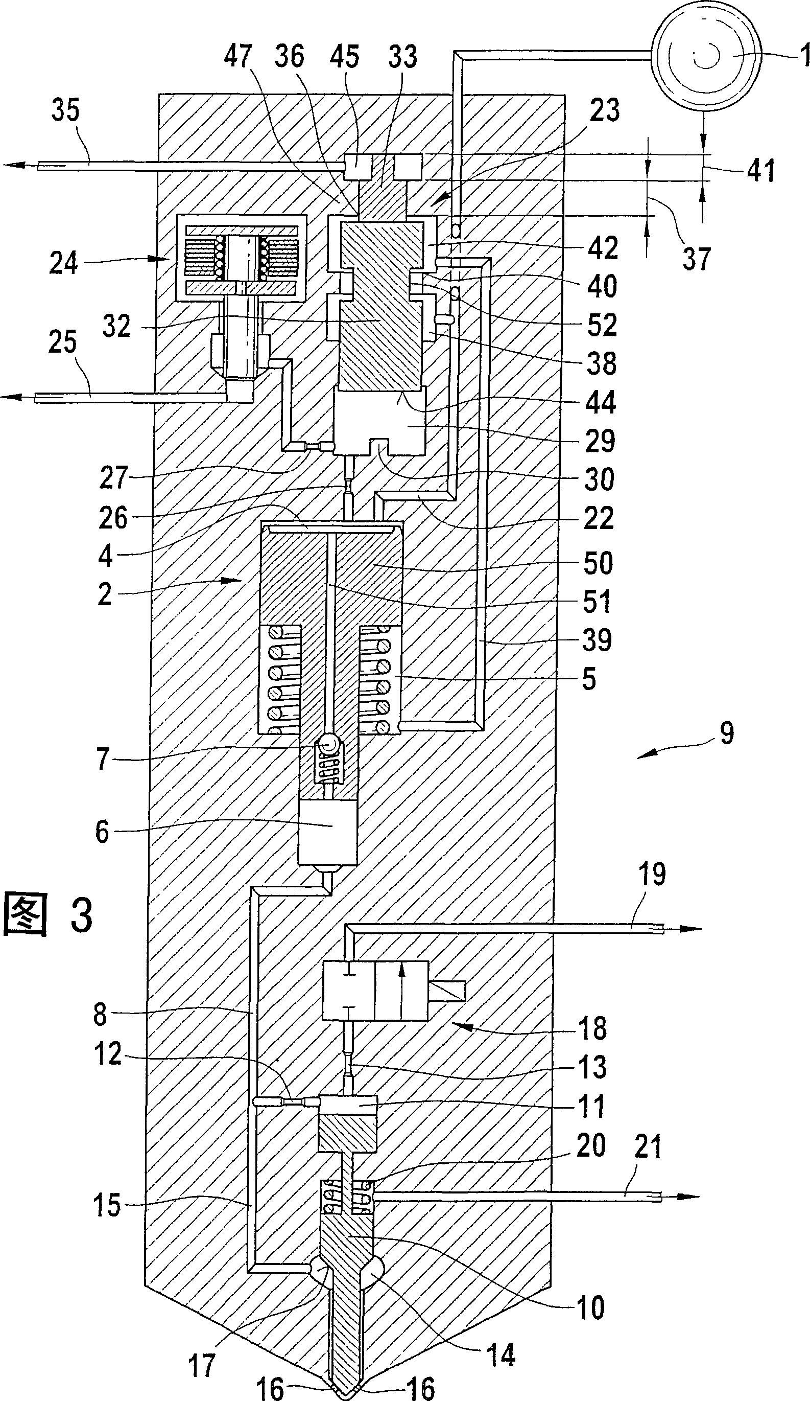
[0018] FIG. 1 shows a servo valve designed as a slide valve for controlling a pressure converter on a fuel injector.

[0019] Via a high-pressure source 1 , which can be a high-pressure accumulator (common rail) or a high-pressure fuel pump, a pressure converter 2 is charged with fuel under high pressure. The pressure transducer 2 comprises a working chamber 4 and a differential pressure chamber 5 (rear chamber), which are separated from one another by a transducer piston 3 . Furthermore, pressure transducer 2 includes a compression chamber 6 . A high-pressure line 8 branches off from this chamber, wherein a non-return valve 7 is accommodated in the refill branch of the pressure transducer 2 .

[0020] The fuel injector 9 is supplied with fuel at a shifted pressure—shifted according to the shift ratio of the pressure converter 2 —via the high-pressure line 8 . The high-pressure line 8 transitions into a nozzle chamber inlet 15 via which the nozzle chamber 14 is supplied with...


PUM


Abstract

A servo valve for actuating a pressure booster of a fuel injector, the pressure booster having a work chamber separated by a booster piston from a differential pressure chamber and the pressure change in the differential pressure chamber of the pressure booster is effected via the servo valve, via switching valve. The control chamber of the servo valve can both be made to communicate with a high-pressure source and pressure-relieved into a low-pressure-side return, and for generating a fast closing motion at the valve piston, a pressure shoulder acting in the closing direction of the valve piston is embodied between the control chamber and the hydraulic chamber, and control edges without a common opening phase are embodied on the valve piston.

Description

technical field [0001] Both pressure-controlled and stroke-controlled injection systems can be used for fueling the combustion chambers of compression-ignition internal combustion engines. In addition to pump-nozzle units, pump-line-nozzle units, accumulator injection systems are used as fuel injection systems. The accumulator injection system (common rail) advantageously enables an adaptation of the injection pressure to the load and speed of the internal combustion engine. In order to achieve a high specific power and reduce the exhaust emissions of an internal combustion engine, the highest possible injection pressure is generally required. Background technique [0002] For reasons of strength, the achievable pressure levels in the accumulator injection systems used today are currently limited to approximately 1600 bar. To further increase the pressure on the accumulator injection system a pressure transducer is used on it. [0003] DE 101 23 910.6 relates to a fuel in...

Claims


Application Information

Patent Timeline
Patent Type & Authority Applications(China)
IPC IPC(8): F02M57/02F02M59/10F02M47/02F02M63/00
CPCF02M47/027F02M59/105F02M63/0005F02M63/0007F02M57/025F02M57/026
Inventor 汉斯-克里斯托夫·马盖尔
Owner ROBERT BOSCH GMBH
Why Eureka
Try Eureka