
Exhaust hood

A technology for exhaust hoods, air, applied in the field of exhaust hoods, which can solve the problems of odor burden and fire hazard, inaccessible fan impeller ventilation channels, unhygienic, etc.

Inactive Publication Date: 2011-08-17
BERLING
View PDF6 Cites 4 Cited by
  • Summary
  • Abstract
  • Description
  • Claims
  • Application Information

AI Technical Summary

Problems solved by technology

Furthermore, the fan wheel and individual air ducts are only inaccessible
This is disadvantageous in exhaust hoods, since here the oil particles and fat particles separate in the individual air ducts, which is unhygienic and leads to odor burden and fire hazard

Method used


Image

  • Exhaust hood
  • Exhaust hood
  • Exhaust hood

Examples


Embodiment Construction

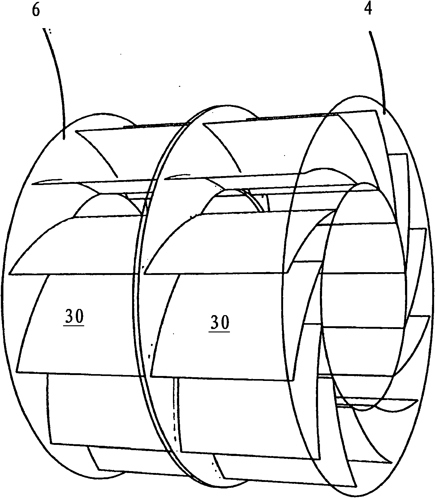
[0027] figure 1A schematic cross-sectional view of the exhaust hood 2 is shown in , in which the first fan wheel 4 and the second fan wheel 6 can be seen. A plurality of guide vanes 8 are arranged around the fan wheels 4 , 6 on the outside. Room air is sucked and accelerated by the first fan wheel 4 through a suction opening 10 and is blown through openings 12 associated with the first fan wheel 4 into the ventilation channels laterally delimited by the guide vanes 8 . In the region of the guide vanes 8 , the room air blown into the ventilation channel (as indicated by the arrows) flows around the second fan wheel 6 .

[0028] Outside air is sucked in by the second fan wheel 6 through the air intake duct 12 and blown through openings 16 associated with the second fan wheel 6 (as also indicated by the arrows) into the ventilation duct laterally delimited by the guide vanes 8 in the way. Since the first fan wheel 4 is separated from the second fan wheel 6 by the partition 18 ...


PUM


Abstract

The invention relates to an exhaust hood (2) comprising a first fan wheel (4) for the intake and removal of indoor air and a plurality of guide vanes (8) arranged externally around the first fan wheel (4) to redirect the air current discharged from the first fan wheel (4). The aim of the invention is to improve said exhaust hood in such a manner that the energy losses through indoor air being blown out are reduced. For this purpose, a second fan wheel (6) for the intake of outdoor air is arranged in the exhaust hood (2) axially offset from the first fan wheel (4) and the air currents discharged from the first and second fan wheel (4, 6) are guided past each other and separately from each other through the guide vanes (8) which are designed as a hollow space (32) and which define air ducts, the walls of the guide vanes (8) defining respective surfaces (34) for the heat exchange between the two air currents.

Description

technical field [0001] The invention relates to an exhaust hood, comprising a first fan impeller for sucking and exhausting indoor air and a plurality of guide blades arranged around the first fan impeller on the outside, and the guide blades are used to make the air flow from the first fan The air flow discharged from the impeller is diverted. Background technique [0002] The same exhaust hood is known from DE 10 2007 051 942.9. Due to the special design and configuration of the guide vanes, it is possible to separate suspended substances contained in the room air, such as oil and grease, from the sucked-in room air at the guide vanes to a special degree. Due to the high air throughput through the exhaust hood, however, considerable energy is lost with the heated or cooled room air. [0003] The use of a heat exchanger in an exhaust hood is known from DE 10 2005 033 224 A1. A heat exchanger is used to heat the cold air coming in from the outside with the help of the war...

Claims


Application Information

Patent Timeline
Patent Type & Authority Applications(China)
IPC IPC(8): F24C15/20F28D9/00
CPCF24C15/20F28D7/106F28D9/0025F28D9/00
Inventor U·贝尔林
Owner BERLING
Learn More