
Light guiding board and backlight module and LCD containing same

A technology of liquid crystal display and light guide plate, applied in the field of light guide plate, can solve the problems of increasing complexity and the like

Inactive Publication Date: 2006-09-06
AU OPTRONICS CORP
View PDF0 Cites 2 Cited by
  • Summary
  • Abstract
  • Description
  • Claims
  • Application Information

AI Technical Summary

Problems solved by technology

However, the complexity of these designs has obviously increased a lot, and there are still shortcomings in its manufacturing and cost

Method used


Image

  • Light guiding board and backlight module and LCD containing same
  • Light guiding board and backlight module and LCD containing same
  • Light guiding board and backlight module and LCD containing same

Examples


Embodiment Construction

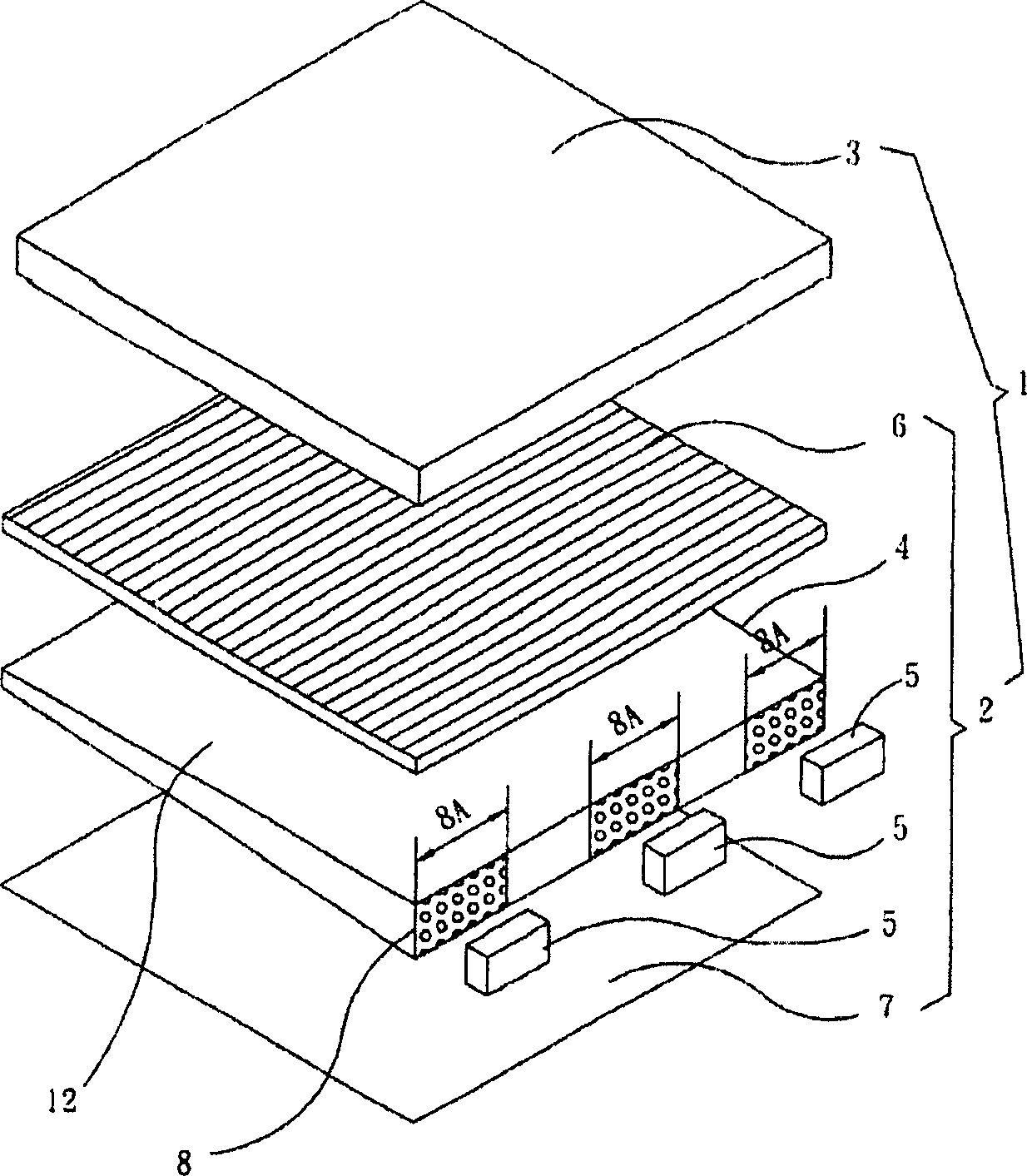
[0029] FIG. 1 is an exploded perspective view of a liquid crystal display drawn according to a first embodiment of the present invention. The liquid crystal display 1 has a liquid crystal panel 3 , at least one optical film 6 and a backlight module 2 . The backlight module 2 is disposed under the liquid crystal panel 3 . The liquid crystal panel 3 generally has an upper and a lower substrate (not shown) and a liquid crystal layer (not shown) disposed between the upper and lower substrates. The upper and lower substrates can be respectively a color filter substrate and an active array substrate, and the backlight module 2 includes a light guide plate 4 and at least one light source. What is shown in this figure is a plurality of light sources.

[0030] For example, the plurality of light sources can be LEDs 5 . In this embodiment, three light-emitting diodes 5 are used for illustration. The light-emitting diodes 5 can be red light-emitting diodes, green light-emitting diodes,...


PUM


Abstract

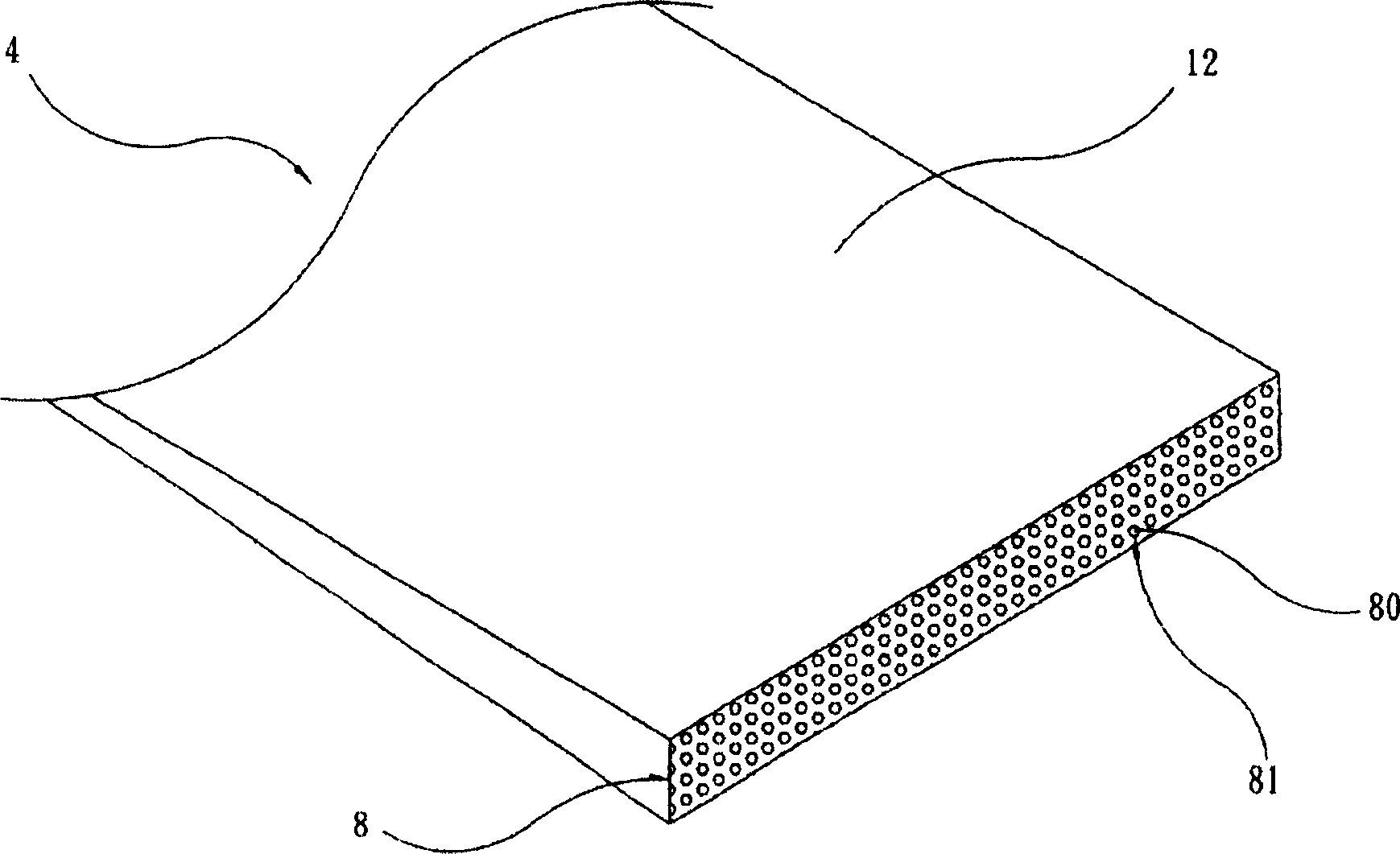
Wherein, the light-input surface of the plate forms at least one surface defined by at least one closed curve. This product can increase diffusion degree of light, and improve whole brightness and evenness.

Description

technical field [0001] The invention relates to a light guide plate for a liquid crystal display, in particular to a light guide plate for a liquid crystal display of a side-light backlight module. Background technique [0002] Liquid crystal displays (liquid crystal displays; LCDs) have largely replaced conventional cathode ray tube (CRT) displays due to their light weight and thin appearance. [0003] Because the liquid crystal panel in the LCD itself does not emit light, it is necessary to provide light to the liquid crystal panel through the backlight module, and apply a voltage to the liquid crystal panel to deflect or tilt the liquid crystal in the liquid crystal panel, so that the light partially penetrates the liquid crystal panel And a display screen is generated. Therefore, the backlight module is a very important light-emitting component in the liquid crystal display. The light source provided by the backlight module, the liquid crystal in the liquid crystal pane...

Claims


Application Information

Patent Timeline
Patent Type & Authority Applications(China)
IPC IPC(8): G02F1/13357G02B6/00G02F1/1335
Inventor 高克嘉陈志光
Owner AU OPTRONICS CORP
Learn More