Heat radiator humidifying device
A humidification device and radiator technology, applied in air humidification system, household heating, heating methods, etc., to achieve the effect of improving economic benefits, simple structure, and excellent humidification effect
- Summary
- Abstract
- Description
- Claims
- Application Information
AI Technical Summary
Problems solved by technology
Method used
Image
Examples
Embodiment 1
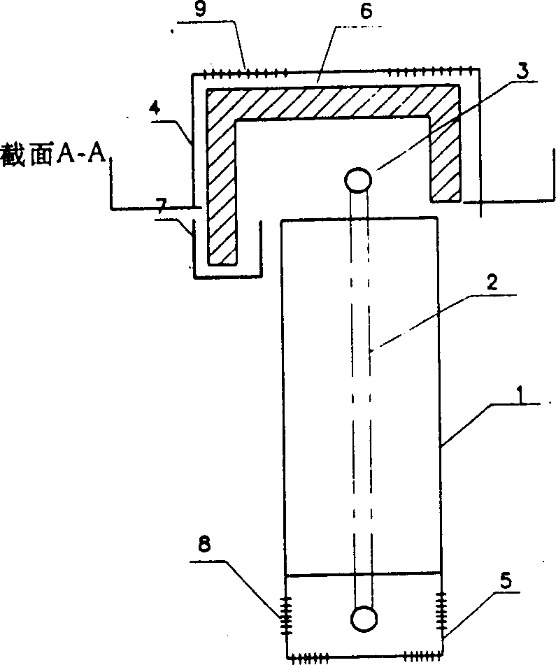
[0049] see figure 1 As shown, a radiator humidifying device according to a preferred embodiment of the present invention mainly includes: a hot air outlet 9 is provided on the upper part of the radiator 1, a cold air outlet 8 is provided on the lower part of the radiator 1, and an air outlet 8 is provided on the upper part of the radiator 1. Cover with upper decorative cover 4, its 1 lower part is covered with lower decorative cover 5, perhaps the top and the bottom of radiator 1 needn't be covered with upper decorative cover 4 and lower decorative cover 5. Heat dissipation branch pipe 3 is connected to supply and return jellyfish pipe 2 see figure 2 .
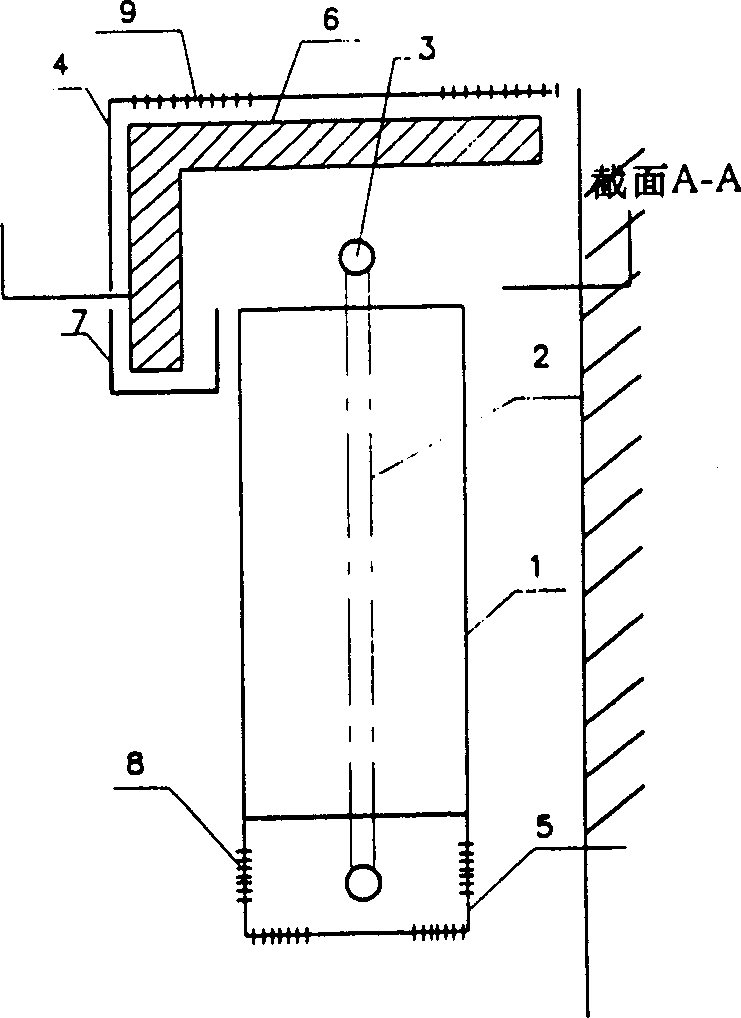
[0050] see figure 2 As shown, it is mainly composed of a radiator 1 with one or more cooling elements with a cavity, a wet film 6 and a water tank 7 . A wet film 6 is provided where the convective airflow of the radiator 1 passes, wherein: the wet film 7 is arranged on the top of the radiator 1, and the wet film 6 on the ...
Embodiment 2
[0052] like image 3 , 5 As shown, a wet film 6 is provided where the convective airflow of the radiator 1 passes, wherein: the wet film 6 is arranged on the upper part of the gap between the radiator 1 and the wall, that is, the upper wet film 6 covers the radiator 1 The front and top surfaces and the wet film on the top surface are placed on the upper part of the gap between the radiator 1 and the wall, wherein the wet film 6 on the front part is placed in the water tank 7 and connected to the water tank 7, and the water tank 7 is connected to the water storage tank catch. The cavity 10 of each cooling element itself is fully enclosed and only ventilated up and down, see Figure 14 . An open cavity 11 is formed between each radiating element of the radiator 1, see Figure 17 . Other structures are with embodiment 1.
Embodiment 3
[0054] like Figure 4 As shown, the wet film 6 is arranged on the upper part of the radiator 1, wherein the wet film 6 covered on the side of the jellyfish pipe 2 is covered on the top surface and the front of the radiator 1, and the wet film 6 on the front is partially placed in the water tank 7 The water tank 7 is connected to the water tank 7, and the wet film 6 covered on the other side of the jellyfish pipe 2 is covered on the top and back of the radiator 1, wherein the wet film 6 on the back is partially placed Be connected with water tank 7 in another water tank 7. Other structures are with embodiment 1.
PUM
 Abstract
Description
Claims
Application Information
 - R&D
- Intellectual Property
- Life Sciences
- Materials
- Tech Scout
- Unparalleled Data Quality
- Higher Quality Content
- 60% Fewer Hallucinations
Browse by: Latest US Patents, China's latest patents, Technical Efficacy Thesaurus, Application Domain, Technology Topic, Popular Technical Reports.
© 2025 PatSnap. All rights reserved.Legal|Privacy policy|Modern Slavery Act Transparency Statement|Sitemap|About US| Contact US: help@patsnap.com


