Rail guided control method and optic disc machine

A control method and a technology of an optical disc drive, applied in optical recording/reproduction, data recording, instruments, etc., can solve the problem of inability to correctly judge the burning/reading power and track error of the alternate point of concave track and convex track Problems such as difficult to read or identify signals or physical marks

Active Publication Date: 2006-08-23
VIA TECH INC
View PDF0 Cites 0 Cited by
  • Summary
  • Abstract
  • Description
  • Claims
  • Application Information

AI Technical Summary

Problems solved by technology

[0007] However, the known technology must constantly detect the tracking error signal or read the physical label field, so when the quality of the optical disc is not good or the optical head is not well controlled when reading the optical disc, it will cause the tracking error signal Or the physical mark is not easy to read or identify, so it is also impossible to correctly judge the alternate point of concave track and convex track to switch different programming / reading power

Method used


Image

  • Rail guided control method and optic disc machine
  • Rail guided control method and optic disc machine
  • Rail guided control method and optic disc machine

Examples


Embodiment Construction

[0033] The tracking control method and the optical disk drive according to the preferred embodiments of the present invention will be described below with reference to related drawings.

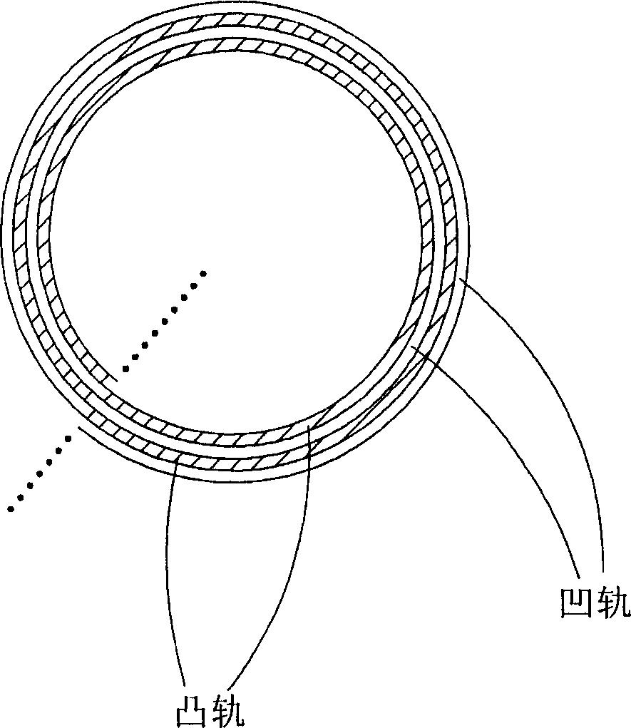
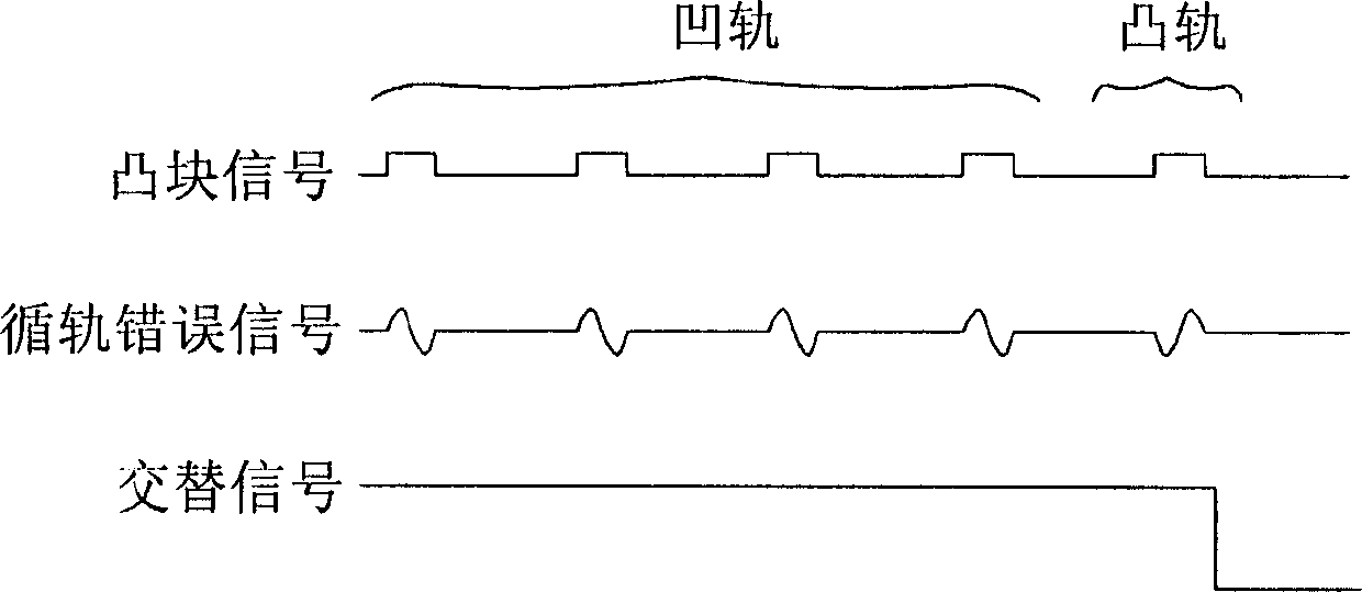
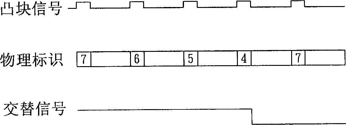
[0034] The track tracking control method according to the preferred embodiment of the present invention controls an optical disc drive to read an optical disc, wherein the optical disc has a plurality of tracks, and the tracks include a plurality of concave tracks and a plurality of convex tracks, and the concave tracks and the convex tracks are alternately connected in series. catch. The tracking control method includes the steps of: detecting a track position read or written by the optical disc drive on the optical disc, then predicting at least one distance count value according to the track position, and generating an alternate signal according to the distance count value to use different Write / read power to write / read grooves and bumps. The track position is a current track in the track...


PUM


Abstract

This invention relates to a guided control method for controlling a disk machine to read a disk sheet with multiple orbits including multiple concave orbits and multiple convex orbits, which are serial alternately, the method includes the following steps: detecting the disk machine to read or write an orbit position in the sheet then forecasting at least a distance counting value according to the orbit position and generating an alternate signal to copy / read the concave orbits or the convex orbits with different copy / read powers, in which, the orbit position is at a current orbit and the distance counting value shows the distance of the current start end to that of a successive orbit.

Description

technical field [0001] The invention relates to a control method of an optical disc drive, in particular to a tracking control method of the optical disc drive. Background technique [0002] In order to allow optical discs to store more data, the new generation of optical disc specifications not only uses lasers with shorter wavelengths, but also changes the track structure of optical discs. [0003] As shown in FIG. 1 , it is a schematic diagram of a conventional DVD-RAM standard optical disc track structure, wherein the optical disc track is formed by alternately connecting groove tracks and land tracks. As shown in Figure 1, the innermost circle of the optical disc is a convex track, the second circle is a concave track, and the third circle is a convex track, which are alternately connected to form a DVD-RAM standard optical disc track structure, in which the concave track and the convex track The alternate connection is called the Land-Groove SwitchPoint. When the opt...

Claims


Application Information

Patent Timeline
Patent Type & Authority Applications(China)
IPC IPC(8): G11B7/09G11B7/00
Inventor 周书弘文治中
Owner VIA TECH INC
Why Eureka
Try Eureka