Industrial pump and manufacturing method thereof

A manufacturing method and an industrial technology, applied to chemical instruments and methods, pumps, components of pumping devices for elastic fluids, etc., can solve problems such as increased costs, lower reliability, and lower sealing effects, and achieve improved Effects of cooling effect and parts cost reduction

Inactive Publication Date: 2006-08-09
HITACHI LTD
View PDF1 Cites 4 Cited by
  • Summary
  • Abstract
  • Description
  • Claims
  • Application Information

AI Technical Summary

Problems solved by technology

[0008] Therefore, it is necessary to close the opening of the envelope chamber after casting with a mechanical seal cover or a part of the box (in the case of Japanese Patent Laid-Open No. 7-305691), or to close the opening of the cooling chamber c with a cover d ( Figure 7 In the case of the cooling unit shown), the structure of the cooling unit becomes complicated, which contributes to an increase in the overall cost of the pump
[0009] In addition, when the casting is cast, defects such as pores are likely to occur, and the reliability is low. At the same time, when the lid d is welded to the opening of the cooling chamber c, a concave section is formed by machining at the opening of the cooling chamber c. part, after welding the cover d in the state of fitting the recessed part, it is necessary to perform operations such as heat treatment for removing the residual stress of the welded part, and machining or welding operations require a lot of man-hours, which is Contributing to the increase in the overall cost of the pump
[0010] On the other hand, such as the Japanese Patent Laid-Open Publication No. 7-305691 or Figure 8 As shown, the cooling chamber c is formed at the boundary part between the box body and the mechanical seal cover or at the boundary part between the shaft sealing shell e and the bracket b, although an O-ring is provided to prevent liquid leakage from the boundary surface f, but because the O-ring f will deteriorate when used at high temperature, the sealing effect will drop soon, so it is necessary to replace it regularly
[0011] However, it is necessary to disassemble the shaft seal device a to replace the O-ring seal f, and the replacement operation requires a lot of time and man-hours, and the operability deteriorates. The power station had to be shut down during the repair period as the pumps were not running

Method used


Image

  • Industrial pump and manufacturing method thereof
  • Industrial pump and manufacturing method thereof
  • Industrial pump and manufacturing method thereof

Examples


Embodiment Construction

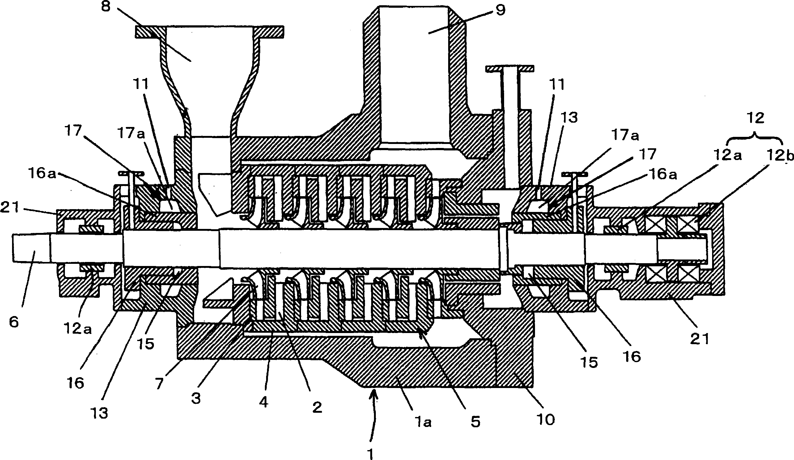
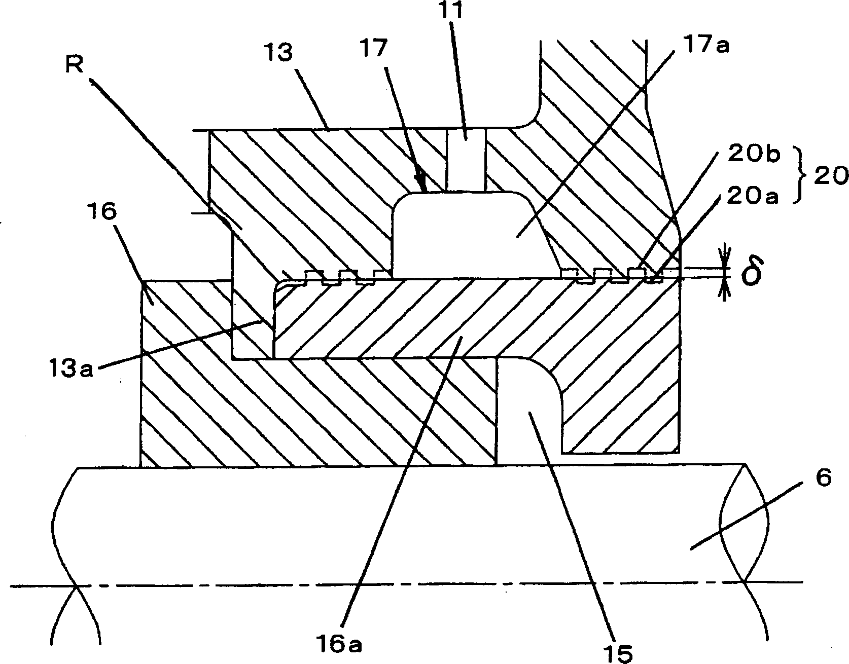
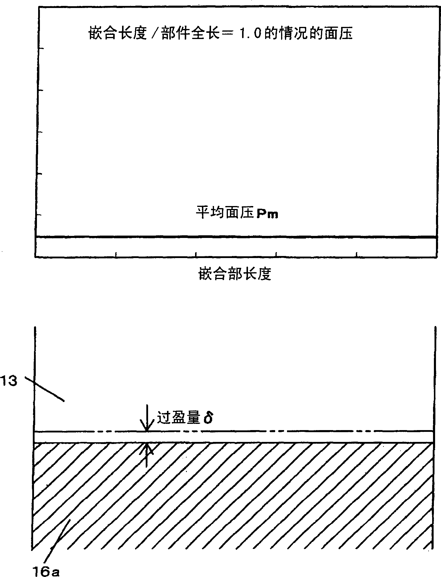
[0028] An embodiment of the present invention will be described in detail with reference to the drawings. figure 1 It is a longitudinal sectional view of a cylindrical multistage turbo pump as an example of an industrial pump, figure 2 yes figure 1 A detailed longitudinal section in the vicinity of the shaft seal of the turbo pump shown. image 3 and Figure 4 It is a schematic diagram explaining the shrink fitting of the shaft seal case of an industrial pump.

[0029] exist figure 1 In the pump main body 1 of the turbo pump shown, an inner case 5 is provided in an outer case 1a called a cylinder case. Multi-stage pump stage (stage)4. The outer case 1a is coaxial with the center of the inner case 5, and the rotation shaft 6 which penetrates the center part of the inner case 5 is provided. An impeller 7 provided on each pump stage 4 is attached to the rotating shaft 6 .

[0030] An inflow port 8 is provided on one end side outer peripheral portion of the outer case 1...


PUM


Abstract

An industrial pump in which bearings provided on a pump main body rotatably support both ends of a rotating shaft to which impellers are mounted. The shaft seal device is arranged adjacent to the bearing. The shaft seal is cooled by cooling water from the outside. The shaft sealing case is fitted to the inner peripheral surface of the bracket housing the shaft sealing device by shrink fitting. Cooling water passes through the boundary between the bracket and the shaft sealing shell. In this way, the operation of welding to block the opening of the cooling unit through which the cooling water passes is omitted.

Description

technical field [0001] The present invention relates to industrial pumps that mainly transfer high-temperature water, such as feed water pumps used in thermal power plants, nuclear power plants, and the like. Background technique [0002] Currently, for example, mechanical seals are used in shaft seals of industrial pumps that mainly transfer high-temperature water, such as boiler feed pumps used in thermal power plants and nuclear reactor feed pumps used in nuclear power plants. Since the shaft seal device becomes high temperature when the pump is operated at a high temperature, it is cooled with cooling water introduced from the outside to prevent deterioration of the shaft seal performance. [0003] In addition, as a cooling method for the shaft seal device, for example, as described in Japanese Patent Laid-Open No. 7-305691, a part of the box body or a part of the mechanical seal cover, or between the box body and the mechanical seal cover, is surrounded by The way the ...

Claims


Application Information

Patent Timeline
Patent Type & Authority Applications(China)
IPC IPC(8): F04D1/08F04D29/58F04D29/08
CPCF04D29/588F04D29/628F04D29/108Y10T29/49243Y10T29/49865B01D63/04B01D69/08B01D2311/165
Inventor 吉田哲也千叶由昌
Owner HITACHI LTD
Why Eureka
Try Eureka