
Brake assembly, particularly for a hydraulic wheel drive

A driving device and hydraulic wheel technology, applied in the directions of brake actuators, brake components, brake types, etc., can solve the problems of system redundancy, problems, and can no longer guarantee the brake function, and save design space and space. Effect

Inactive Publication Date: 2010-04-28
LOHMANN & STOLTERFOHT
View PDF6 Cites 0 Cited by
  • Summary
  • Abstract
  • Description
  • Claims
  • Application Information

AI Technical Summary

Problems solved by technology

[0005] The disadvantage of this solution is that this common actuation of a single brake piston is problematic in terms of safety measures, since system redundancy is basically abandoned here
If the common brake piston fails, the function of the brake is no longer guaranteed even if the piston is actuated via another hydraulic circuit

Method used


Image

  • Brake assembly, particularly for a hydraulic wheel drive
  • Brake assembly, particularly for a hydraulic wheel drive

Examples


Embodiment Construction

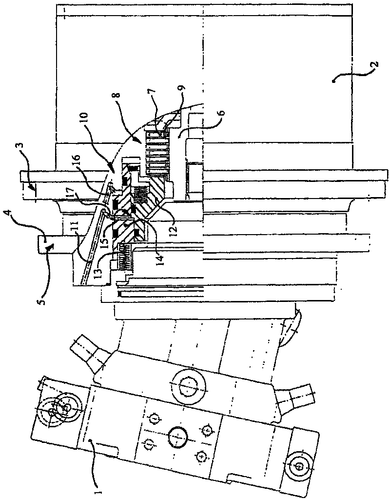
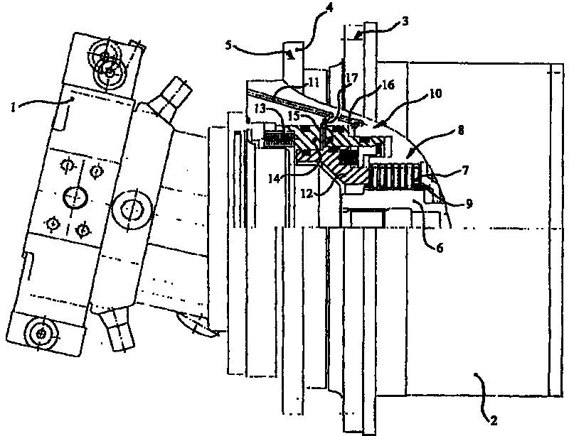
[0017] The wheel drive essentially consists of a hydraulic motor 1 which is flanged to a planetary gearbox 2 and whose housing is provided with holes 3 for the connection of a motor vehicle wheel (not further shown in the figures). The wheel drive further comprises a support shaft 4, through an outer radial hole 5 of the support shaft, the entire wheel drive is mounted on a motor vehicle (not further shown in the figures).

[0018] The inner disk 7 of the disk pack 8 is arranged on the drive side of the planetary gearbox 2 on the drive shaft 6 interacting with the hydraulic motor 1 . The inner disk 7 interacts with a relatively narrow outer disk 9 of the disk package 8 , which is fixedly arranged relative to the bearing shaft 4 .

[0019] The friction plate set 8 can be braked by pressing the piston structure 10 . The piston arrangement 10 consists of a service brake piston 12 , which is pressed by a first hydraulic circuit 11 , and a parking brake piston 14 , which is presse...


PUM


Abstract

The invention relates to a brake assembly, particularly for a hydraulic wheel drive, comprising a packet of plates (8), which consists of a number of outer plates (9) and of corresponding inner plates(7), and which, for braking, can be pressed together by a piston assembly (10). A first hydraulic circuit (11) provided for service braking acts upon the piston assembly (10), and a second hydrauliccircuit (16) provided for parking braking acts upon the piston assembly (10) that comprises a service braking piston (12), which is in contact with the packet of plates (8) and which is acted upon bythefirst hydraulic circuit (11). Said service braking piston can acted upon by an adjacent separate parking brake piston (14) which interacts with the second hydraulic circuit (16).

Description

technical field [0001] The present invention relates to a brake structure, especially a brake structure for a hydraulic wheel drive device. The brake structure has: a friction plate group composed of a plurality of outer friction plates and corresponding inner friction plates, which can be pressed together by a piston structure. For braking, the first hydraulic circuit acts on the piston structure for service braking, and the second hydraulic circuit acts on the piston structure for parking brake. [0002] The field of application of the invention extends mainly to agricultural machinery technology. Agricultural vehicles are often equipped with a wheel drive, which consists of a hydraulic motor as drive unit, to which is connected a compact planetary gearbox as a stage drive, the internal gear of which is connected directly to the wheel hub. A motor vehicle equipped with such a wheel drive has, on the one hand, a so-called dynamic brake which, as a service brake, enables the ...

Claims


Application Information

Patent Timeline
Patent Type & Authority Patents(China)
IPC IPC(8): F16D55/40F16D59/02F16D65/14F16D65/18F16D55/00
CPCF16D2123/00F16D2121/02F16D2055/0058F16D65/186F16D2121/12F16D55/40
Inventor 雷蒙德·格林伯恩哈德·朗根贝克
Owner LOHMANN & STOLTERFOHT
Learn More