
Flexible pressurizing and damping device for drill bit

A shock-absorbing device and a flexible technology, applied in the direction of drill pipes, drill pipes, drilling equipment, etc., can solve the problems of low drilling pressure, difficult to control the drilling rate, and low ROP

Inactive Publication Date: 2006-07-26
祝兆清
View PDF0 Cites 7 Cited by
  • Summary
  • Abstract
  • Description
  • Claims
  • Application Information

AI Technical Summary

Problems solved by technology

[0002] In the prior art, in the conventional drilling process, the drill bit is directly connected to the lower end of the drill string, and the WOB is provided by the weight of the drill string on the upper part of the drill bit. This method has many disadvantages: ① It is difficult to maintain stable WOB, and it is difficult to control the drill rate; Low drilling pressure, low drilling speed, and low ROP; high drilling pressure seriously affects the life of the drill bit, and the drill string is also prone to fatigue damage
② Drilling in special formations such as gravel layers may cause drill jumping. To solve the problem of drill jumping, various shock absorbers have been designed, but the damping effect is limited and cannot meet the site requirements
③To avoid deviation and straighten, the method of hanging is often used. Although this method is effective, it is realized at the expense of ROP.
In the special drilling process: ①Deep wells, highly deviated wells or horizontal wells, due to the influence of the gravity component of the drill string, buoyancy, friction and other factors, will produce "false WOB" phenomenon, it is difficult to obtain ideal WOB, so that Operate blindly
②Slim hole drilling, due to the small size, light weight and poor rigidity of the drill string, it is difficult to pressurize, which greatly affects the drilling efficiency
This traditional rigid pressurization method has many unavoidable disadvantages (such as uneven feeding of drills, jumping drills, bending of drilling tools, false drilling pressure, etc.), which seriously affects the ROP and the life of drill bits and drilling tools.

Method used


Image

  • Flexible pressurizing and damping device for drill bit
  • Flexible pressurizing and damping device for drill bit
  • Flexible pressurizing and damping device for drill bit

Examples


Embodiment Construction

[0025] Such as figure 1 As shown, this example consists of an upper joint 1 that can be connected with the drill string, two sets of hydraulic boosters 2, a power flexible converter 3 and a lower joint 4 that can be connected with the drill bit. The pressure booster 2 is connected to the upper joint 1, two groups of hydraulic boosters 2 are connected in series, and the hydraulic booster 2 at the bottom is connected to the power flexible converter 3.

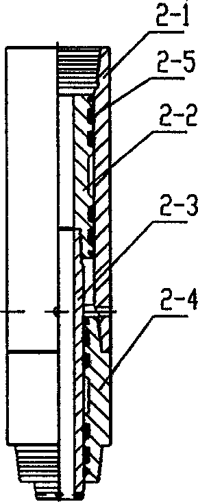
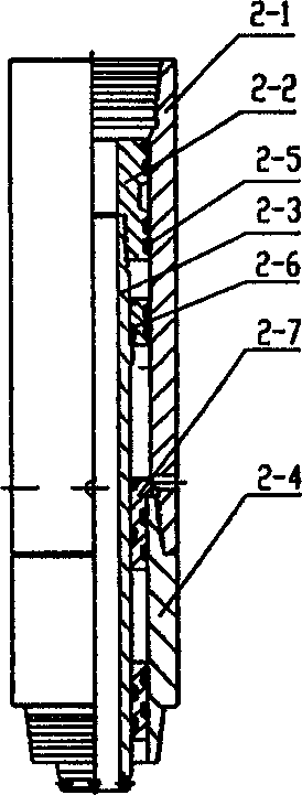
[0026] Such as figure 2 , the hydraulic booster 2 is mainly composed of a hydraulic cylinder A 2-1, a hollow piston A 2-2, a hollow central shaft 2-3, and a shaft sleeve A 2-4. The upper end of the hydraulic cylinder A 2-1 Set the internal thread threadedly connected with the upper joint or with the lower end of the shaft sleeve A 2-4 of the previous group of hydraulic booster 2, the shaft sleeve A 2-4 is threaded at the lower end of the hydraulic cylinder barrel A 2-1, and the piston A 2 -2 is threadedly connected with the ce...


PUM


Abstract

The invention relates to a drill head flexible pressurizing damping device, belonging to the circle drill well device of water power or slurry. It at least comprises one hydraulic pressurizing device connecting to the drill post and one power flexible transformer connecting the drill head. Wherein, the hydraulic pressuring device comprises a hydraulic cylinder, a hollow piston, a hollow central axle, and an axle sleeve, while the upper end of hydraulic cylinder comprises a connection element connecting the drill post; the power flexible transformer comprises a hydraulic cylinder, a hollow piston, a hollow key axle, a key sleeve, and an axle sleeve. The invention can be mounted between drill post and the drill head to transmit the axial power generated by the rotational torque on the rotational disc of drill post and the hydraulic pressurizing device to the drill head without expending water power and adsorb the vibration at most; when in high drill pressure and high mechanical drill speed, it has the functions of inclined resistance and stabilization. It can improve the mechanical drill speed around 40%, and prolong the service life of drill head, drill device and the ground device.

Description

technical field [0001] The invention belongs to the technical field of hydraulic or mud circulation drilling equipment. Background technique [0002] In the prior art, in the conventional drilling process, the drill bit is directly connected to the lower end of the drill string, and the WOB is provided by the weight of the drill string above the drill bit. This method has many disadvantages: ① It is difficult to maintain stable WOB, and it is difficult to control the drill rate; Low drilling pressure, low drilling speed, and low mechanical penetration rate; high drilling pressure seriously affects the life of the drill bit, and the drill string is also prone to fatigue damage. ② Drilling in special formations such as gravel layers may cause drill jumping. In order to solve the problem of drill jumping, various shock absorbers have been designed, but the damping effect is limited and cannot meet the site requirements. ③The anti-deviation and straightening method is often use...

Claims


Application Information

Patent Timeline
IPC IPC(8): E21B17/07
Inventor 祝兆清
Owner 祝兆清
Learn More