Seal for a pressurized container

A technology for pressure vessels and sealing components, applied in structural parts, electrical components, battery pack components, etc., can solve problems such as the dependence of sealing components

Inactive Publication Date: 2006-07-12
EVEREADY BATTERY CO INC
View PDF3 Cites 1 Cited by
  • Summary
  • Abstract
  • Description
  • Claims
  • Application Information

AI Technical Summary

Problems solved by technology

While the sealing assembly allows the electrochemical cell to be safely vented, the sealing assembly relies on the use of an inner cover

Method used


Image

  • Seal for a pressurized container
  • Seal for a pressurized container
  • Seal for a pressurized container

Examples


Embodiment Construction

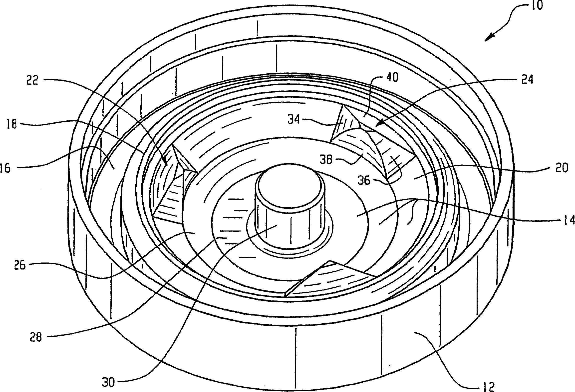
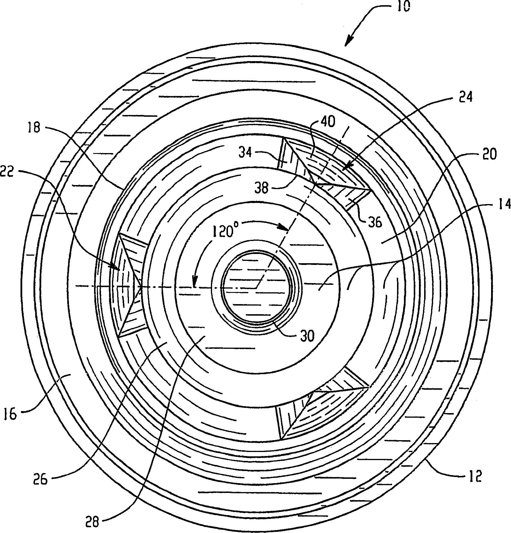
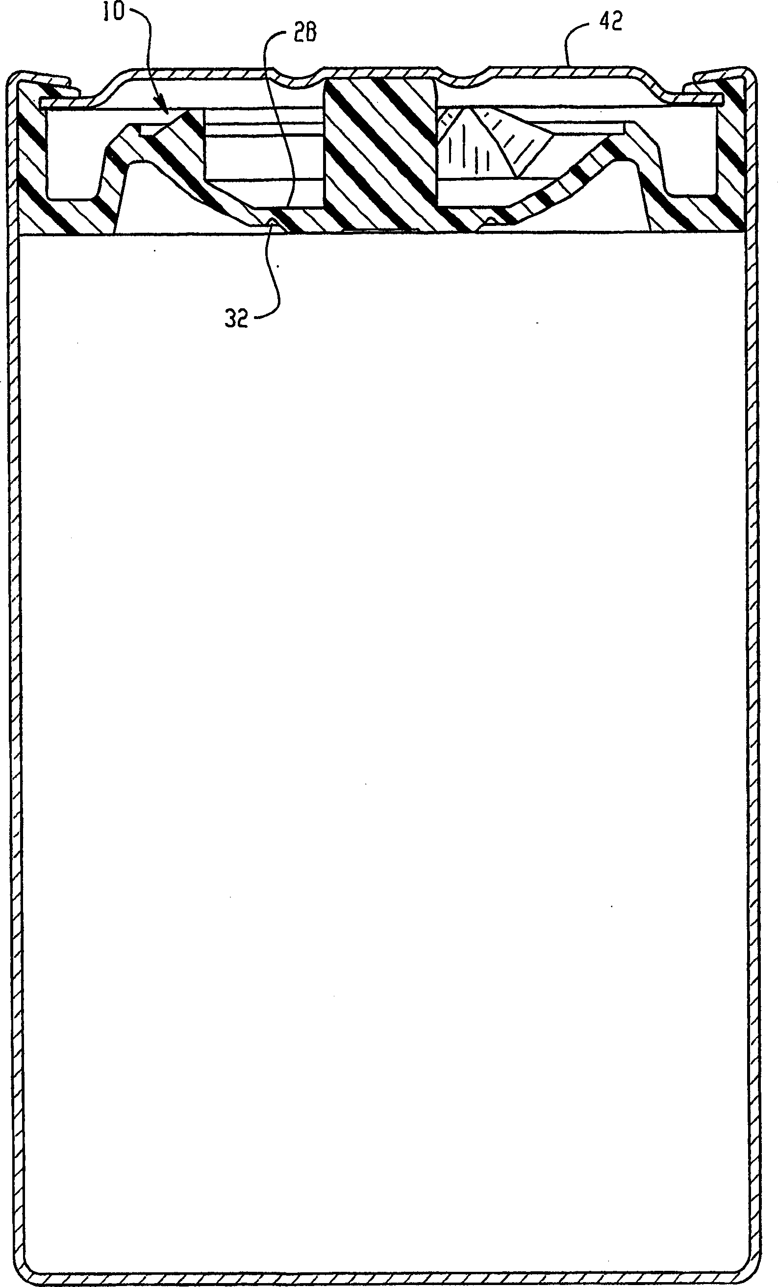
[0016] figure 1 6 to 6 show various views of a sealing member and a pressure vessel including one of said sealing members. Taken together, these drawings and the following description teach those skilled in the art how to practice the claimed invention. In one aspect, the invention is a pressure vessel 50 having a vent assembly 52 including a sealing member 10 and at least one cover 42 . The vent assembly covers the opening 54 in the pressure vessel wall 56 and is secured to the vessel. The vent assembly functions as a pressure-activated safety valve that releases the pressure in the container when the pressure exceeds a predetermined value. The sealing member 10 has a design that can be ruptured along a line of weakness 32 in the membrane region 28 of the sealing member. The torn septum then flexes towards the lid 42 in response to the gas being expelled from within the container. Due to the presence of two or more protrusions 22 and 24 protruding from the upper surface 1...


PUM


Abstract

A pressurized container with a vent assembly that reliably prevents resealing of a vented seal member is provided. In one embodiment, the vent assembly seals the end of a container that includes a first electrode, a second electrode, a separator located between the first and second electrodes and an electrolyte in contact with the electrodes and separator. The seal member includes at least two protrusions on the surface of the seal member. The protrusions define and maintain a gap between the cover and seal member after the seal member has ruptured thereby allowing pressure within the container to be reduced.

Description

technical field [0001] This invention relates generally to ventable seals for pressure vessels and, more particularly, to hermetically sealed electrochemical cells. Background technique [0002] Pressure vessels are used in a wide range of applications. Among these applications are: aerosol spray containers; storage containers for compressed gases commonly used in industrial settings; and cylindrical batteries containing electrochemically active materials that generate gases when reactions between chemical species occur. The batteries that millions of consumers buy to power a wide variety of devices essentially form a unique class of pressure vessels that must withstand very high internal pressures while also including Large case rupturable vent through which gas can escape. If a pressure vessel does not have a reliably rupturable vent, and the pressure exceeds the burst strength of the vessel, the vessel may rupture in an unpredictable and potentially damaging manner. ...

Claims


Application Information

Patent Timeline
IPC IPC(8): H01M2/12
CPCY02E60/12H01M2/1241Y02E60/10H01M50/3425
Inventor R·M·詹米
Owner EVEREADY BATTERY CO INC
Why Eureka
Try Eureka