
Low head, dynamic variable pitch, submersible hydro generator

A technology for hydroelectric generators and generators, which is applied to the control of generators, ocean energy power generation, engine components, etc. It can solve the problems of doubtful reliability and high cost, and achieve the effect of no pollution and increased power generation

Inactive Publication Date: 2006-06-28
尤金・G・利格曼
View PDF7 Cites 9 Cited by
  • Summary
  • Abstract
  • Description
  • Claims
  • Application Information

AI Technical Summary

Problems solved by technology

However, this market has not yet been widely opened because there is no reliable hydraulic technology, or there is reliable hydraulic technology, which is usually too expensive and the reliability is still questionable.

Method used


Image

  • Low head, dynamic variable pitch, submersible hydro generator
  • Low head, dynamic variable pitch, submersible hydro generator
  • Low head, dynamic variable pitch, submersible hydro generator

Examples


Embodiment Construction

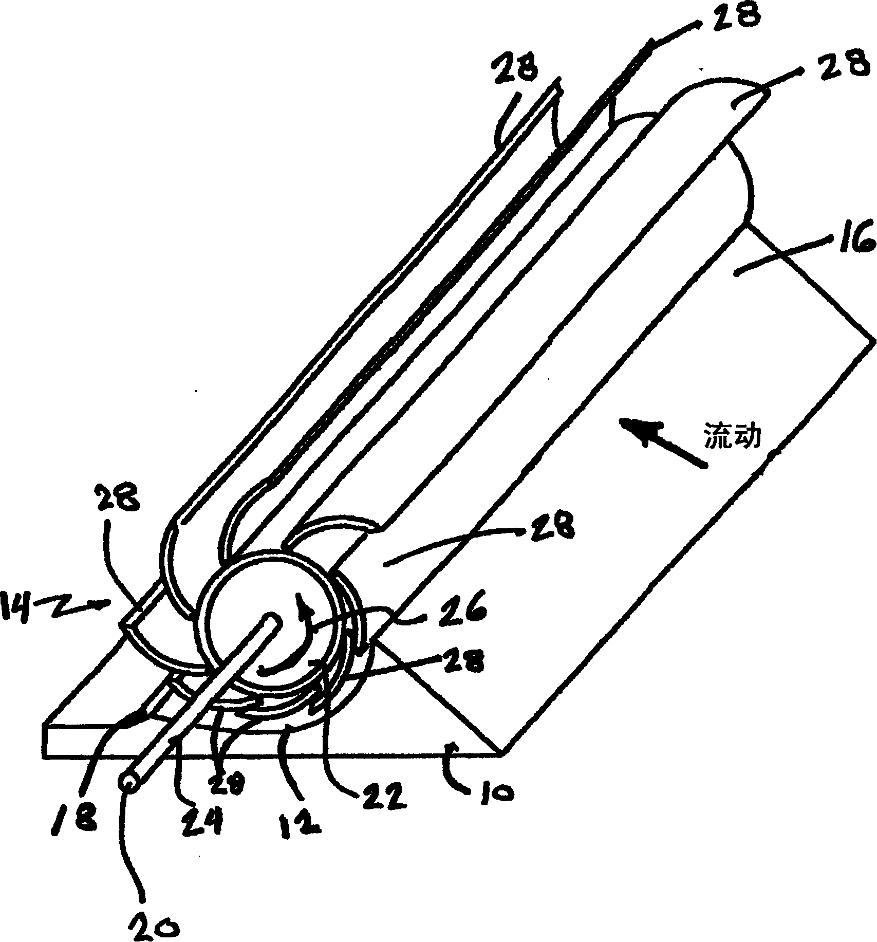
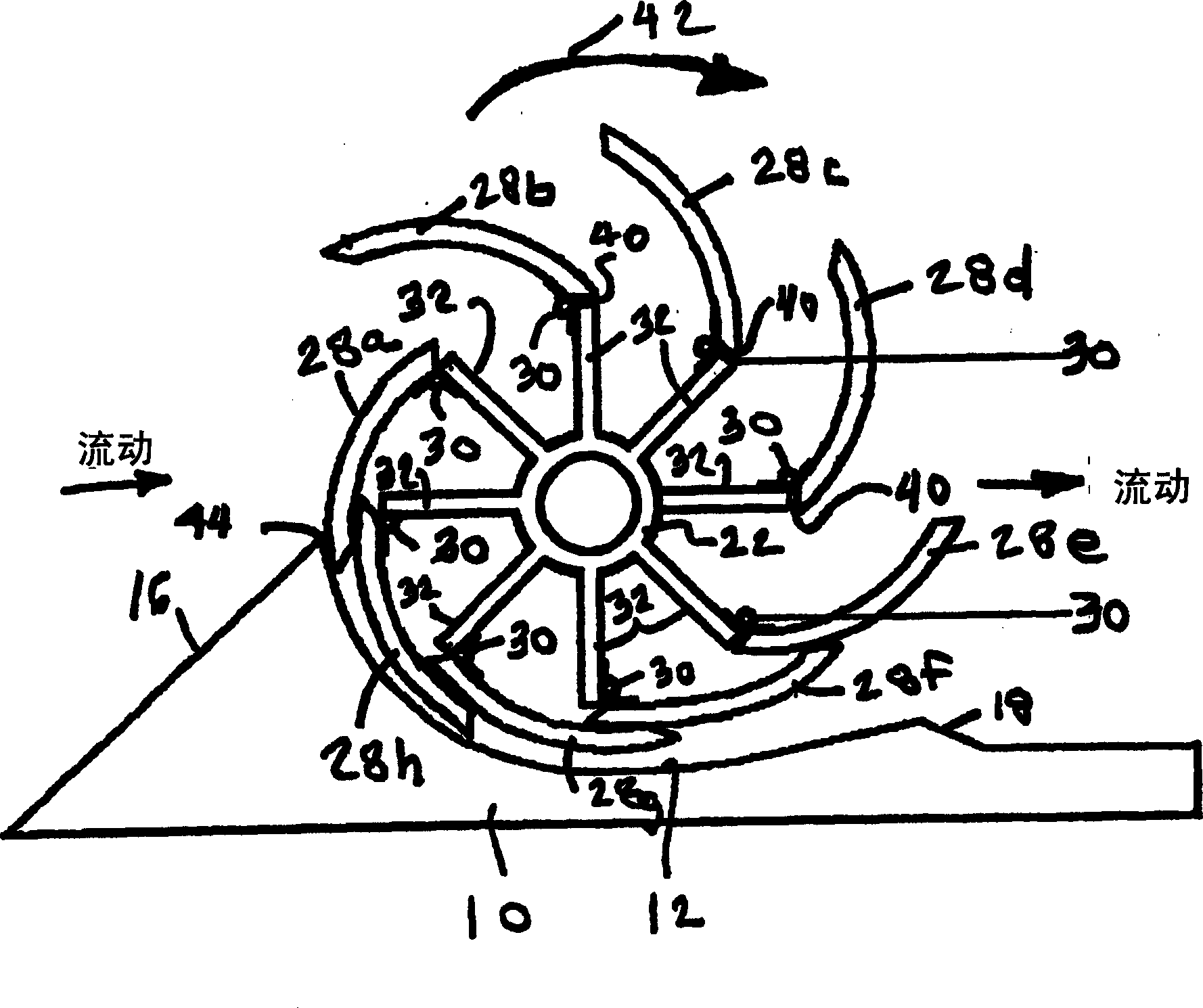
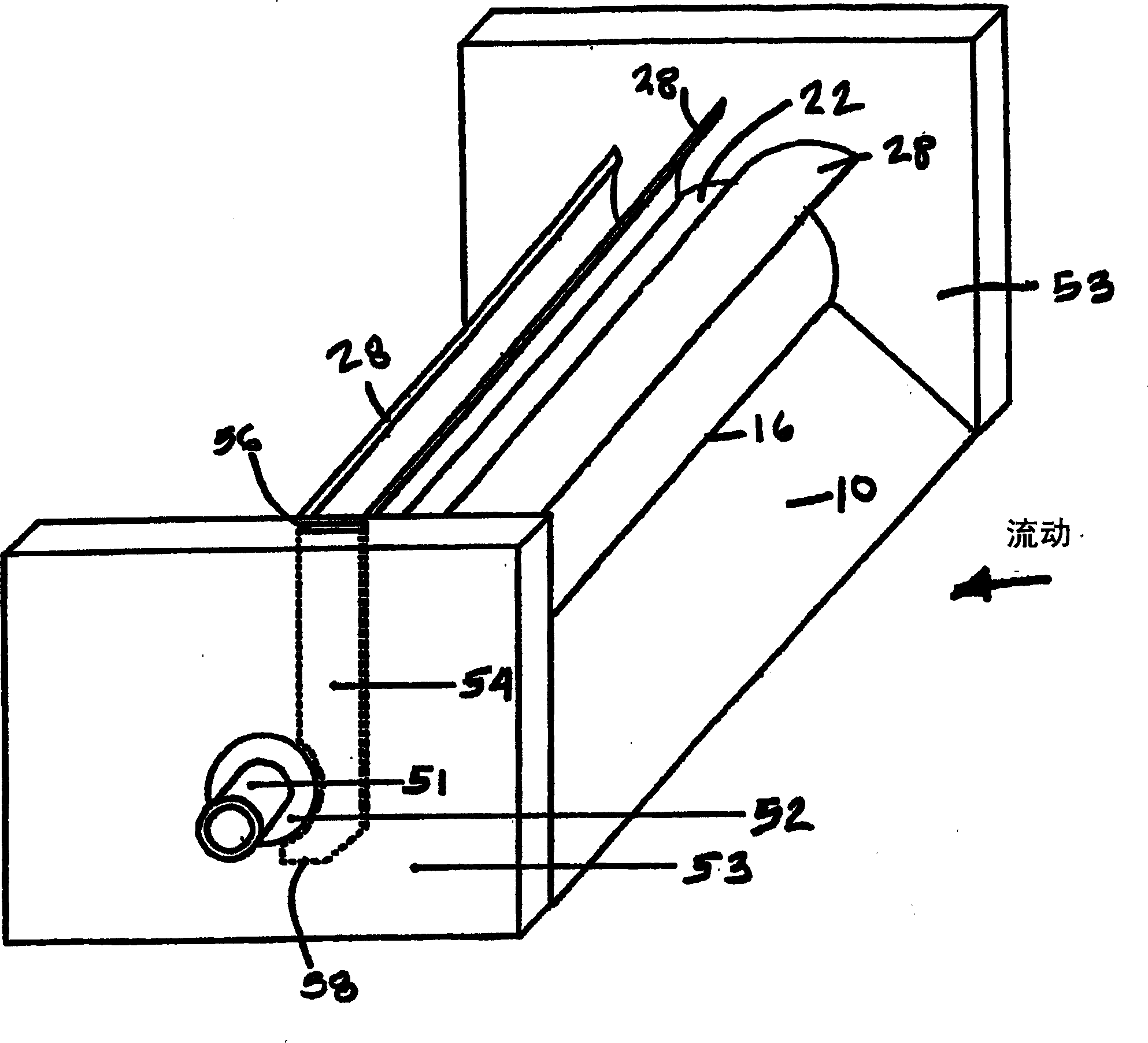
[0036] figure 1 Basic working components are shown. The base 10 is provided so that it is suitable for installation on the bottom surface of a waterway. The longitudinal axis of the base extends to the width or span of the channel and is perpendicular to the direction of flow. In a preferred embodiment, the base is constructed of a heavy inert material such as reinforced concrete. The base can also consist of a hollow high strength plastic so that the hollow can be filled with concrete at the installation site. The base includes a shaped slot 12 for receiving a mandrel and blade assembly 14 . The upstream side 16 of the base is higher than the downstream side 18 and the vane assembly ensures that water flows into the system above the axis of rotation 20 of the mandrel 22 . An axial power shaft 24 connects the spindle. Arrow 26 indicates the direction of rotation.

[0037] Typically, the mandrel 22 is made of a material having high stiffness and high fracture toughness, s...


PUM


Abstract

The hydroelectric generator system includes a rotor that rotates about an axis on its base, and a plurality of blades hinged to the rotor and extending radially outward from the rotor. These blades are designed to expand on the upstream side to a fully extended position during a partial revolution of the rotor, where water flow from the upstream side to the downstream side hits the blades and opens them to the fully extended position to drive the rotor. The rotor or rotor and blades can be completely submerged in water.

Description

[0001] claim priority [0002] This application claims priority to US Provisional Application No. 60 / 473717, filed May 27, 2003. technical field [0003] The present invention relates generally to systems for generating and distributing hydroelectric power, and in particular to a micro hydroelectric system for generating electricity from low flow rivers and the like. Background technique [0004] Hydropower plants are generally classified as "low" or "high" head. Low head generally refers to elevation changes of less than 10 feet (3 meters). In the past, vertical drops below 2 feet (0.6) meters have generally not provided usable hydroelectric systems. High flow rates can compensate for low heads, but larger and more expensive turbines are necessary. In particular, prior art turbines do not operate efficiently at very low heads and flows. [0005] The amount of power available depends on the dynamic head, water flow and efficiency of the turbine / generator combination. To...

Claims


Application Information

Patent Timeline
IPC IPC(8): F03B13/00F03B13/10F03B13/12F03B17/06H02K7/18H02P9/04
CPCF03B17/065H02K7/1823Y02E10/30
Inventor 尤金·G·利格曼
Owner 尤金・G・利格曼
Learn More