Method for driving plasma display panel

A technology of plasma display screen and driving method, which is applied in the direction of static indicators, instruments, etc., and can solve the problems of uneven luminous brightness, error, and different luminous intensity of the screen

Inactive Publication Date: 2006-06-14
PANASONIC CORP
View PDF1 Cites 2 Cited by
  • Summary
  • Abstract
  • Description
  • Claims
  • Application Information

AI Technical Summary

Problems solved by technology

[0007] In the display screen of this existing method, there is an error in the timing of discharge generation in each discharge unit according to the display s...

Method used


Image

  • Method for driving plasma display panel
  • Method for driving plasma display panel
  • Method for driving plasma display panel

Examples


Embodiment Construction

[0018] The driving method of the plasma display screen in an embodiment of the present invention will be described below with reference to the accompanying drawings.

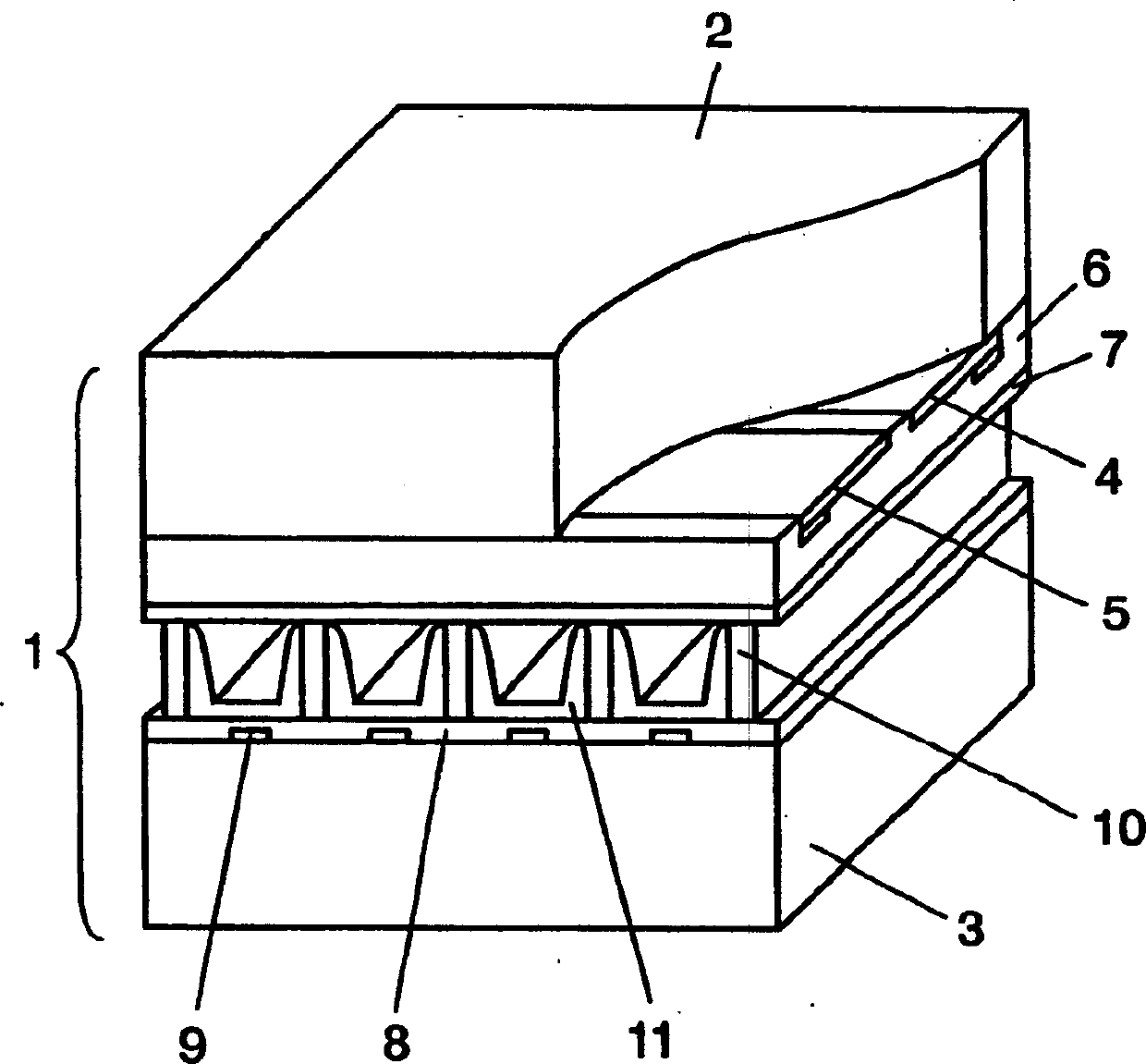
[0019] FIG. 1 is a perspective view showing a main part of a display screen used in an embodiment of the present invention. The display panel 1 is configured such that a front substrate 2 and a rear substrate 3 made of glass are arranged facing each other, and a discharge space is formed therebetween. Viewed from the side of the front substrate 2, there are formed on the front substrate 2 a plurality of pairs of scan electrodes 4 and sustain electrodes 5 that are parallel to each other and form display electrodes. Dielectric layer 6 is formed to cover scan electrodes 4 and sustain electrodes 5 , and protective layer 7 is formed on dielectric layer 6 .

[0020] A plurality of data electrodes 9 covered by an insulator layer 8 are attached to the back substrate 3 , and partition walls 10 are provided on the insula...


PUM


Abstract

The invention discloses a driving method for a plasma display screen. The method can reduce the occurrence of uneven areas of luminous brightness on each screen, and can keep the voltage and pulse width of the pulse unchanged, so that the increase in power consumption can be suppressed. big. In this plasma display panel driving method, discharge cells are formed at intersections of scan electrodes, sustain electrodes, and data electrodes, and include an initializing period for generating initial discharge in the discharge cells, and an address period for generating address discharge in the discharge cells. , and the sustain period during which sustain discharge occurs by alternately applying sustain pulses to the scan electrodes and sustain electrodes of the discharge cells. rising edge time.

Description

technical field [0001] The invention relates to a driving method of a plasma display screen. Background technique [0002] In a typical AC surface discharge display panel as a plasma display panel (hereinafter simply referred to as a display panel), many discharge cells are formed between a front panel and a rear panel arranged to face each other. On the front plate, multiple pairs of display electrodes consisting of a pair of scan electrodes and sustain electrodes are formed parallel to each other on the front glass substrate, and a dielectric layer and a protective layer are formed to cover the display electrodes. On the back plate, a plurality of parallel data electrodes, a dielectric layer covering the data electrodes, and a plurality of partition walls parallel to the data electrodes are respectively formed on the rear glass substrate. Then, phosphor layers are formed on both the surface of the dielectric layer and the side surfaces of the...

Claims


Application Information

Patent Timeline
IPC IPC(8): G09G3/20G09G3/288G09G3/291G09G3/292G09G3/294G09G3/296G09G3/298
CPCG09G3/294G09G3/2965G09G2310/066G09G2320/0233
Inventor 美马邦启木村雅典木村悌一
Owner PANASONIC CORP
Why Eureka
Try Eureka