
Optical code reader with autofocus and interface unit

A technology of optical reading and optical mechanics, applied in optics, optical components, instruments, etc., can solve problems such as limited success

Inactive Publication Date: 2006-06-14
SYMBOL TECH INC
View PDF5 Cites 11 Cited by
  • Summary
  • Abstract
  • Description
  • Claims
  • Application Information

AI Technical Summary

Problems solved by technology

Each of these proposed schemes has produced limited success

Method used


Image

  • Optical code reader with autofocus and interface unit
  • Optical code reader with autofocus and interface unit
  • Optical code reader with autofocus and interface unit

Examples


Embodiment Construction

[0034] Reference is now made in detail to the drawings in which like reference numerals designate like or identical elements throughout the views.

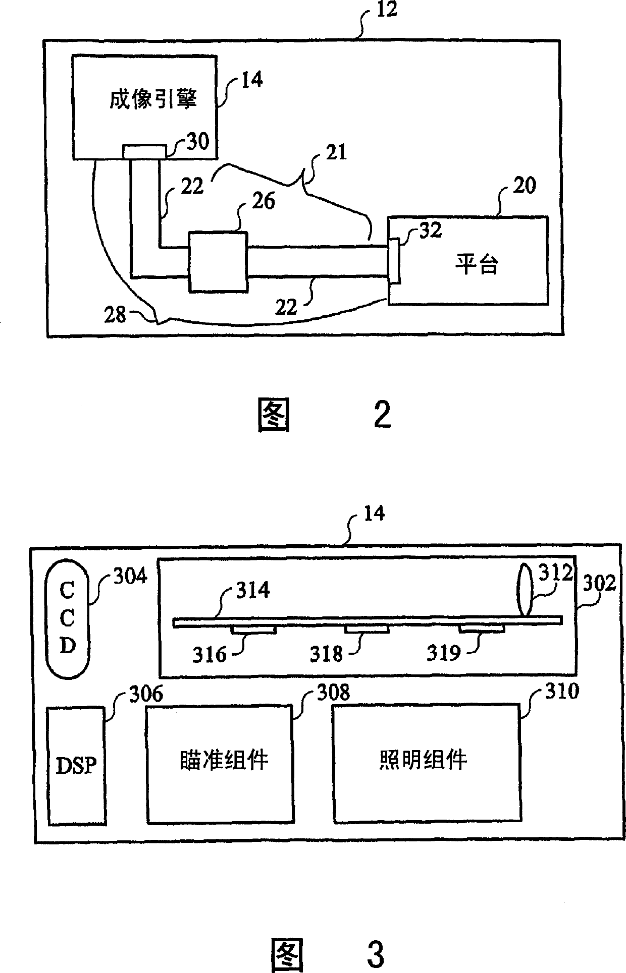
[0035] FIG. 1 shows an optical code reader system 10 including an optical code reader 12 having an imaging engine 14 , wherein the optical code reader 12 is preferably connected to a host terminal 16 by a cable 18 . FIG. 2 shows a block diagram of the optical code reader 12 in which the imaging engine 14 is connected to the platform 20 through an interface. Transmission assembly 21 includes at least one connector 22 and / or at least one transmission adapter device 26, wherein in order to provide electrical and / or data communication between imaging engine 14 and platform 20, device 26 has separate or combined electrical and / or data transmission circuit.

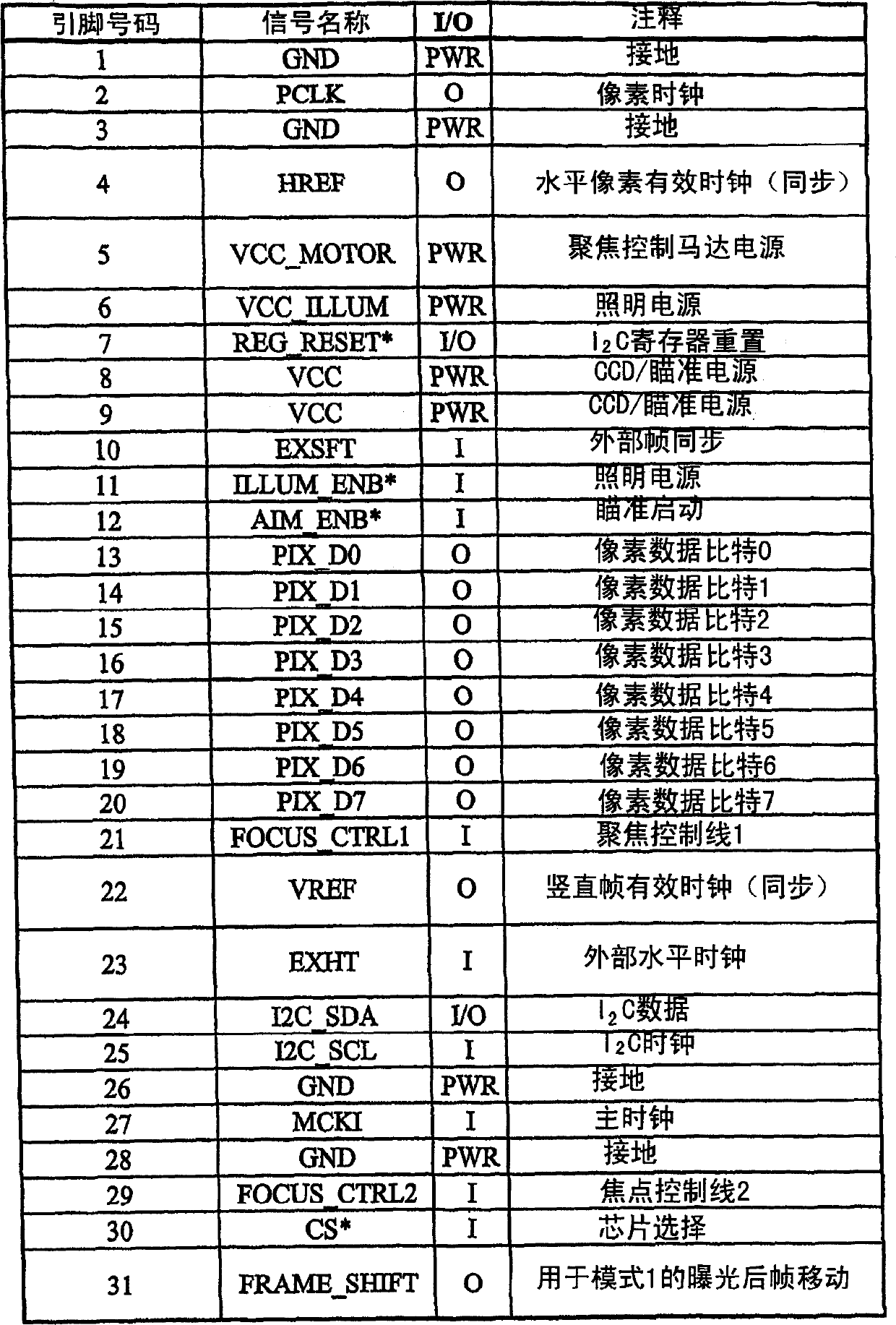
[0036] Interface assembly 28 for providing data and / or electrical communication between imaging engine 14 and platform 20 includes input / output (I / O) devices 30 of imaging engine ...


PUM


Abstract

An optical code reader (12) having structure for focusing an imaging optical assembly onto a target image. The optical code reader includes a chassis (910) and an imaging optics assembly (914) pivotally mounted on the chassis. The imaging optics are placed within the optomechanical barrel assembly. Pivoting of the optomechanical barrel assembly adjusts the focus of the imaging optics on the target image. The optical code reader also includes an illumination device (918) and an aiming device (920). An interface assembly (28) connects the imaging engine (14) of the imaging optics assembly to the circuit assembly of the optical code reader. The imaging engine (14) is removably positioned and / or sized and configured to fit a predetermined build factor.

Description

technical field [0001] This invention relates to imaging in optical code reading devices, and more particularly to handheld code readers based on solid-state image tubes positioned at variable orientations and distances from a target code. Background of the invention [0002] Optical codes are patterns composed of image regions with different light reflection or light emission properties, which are usually combined according to a priori rules. The term "barcode" is often used to describe certain types of optical codes. The optical properties and pattern of the optical code are chosen to distinguish its appearance from its background environment. Barcode scanners are one type of equipment used to recognize or extract data from optical codes, sometimes called "optical code readers." [0003] Optical code readers are used in fixed and portable installations in many different environments, such as checkout services in shopping malls, workflow and inventory control in manufactu...

Claims


Application Information

Patent Timeline
IPC IPC(8): G06K7/10G02B7/04G02B7/09
Inventor 爱德华·科根约瑟夫·佐丹奴梅于尔·帕特尔T·D·史托马斯·比安库利张珩尼古拉斯·布翁乔瓦诺安德烈·沙姆科维奇
Owner SYMBOL TECH INC
Learn More