Fluid bearing device

A technology of fluid bearings and bearing components, applied in the directions of bearings, shafts and bearings, mechanical equipment, etc., can solve the problems of bearing rigidity decline, bearing distortion, adverse effects of NRRO, etc., and achieve the effect of stable transportation and handling

Inactive Publication Date: 2006-06-07
NTN CORP
View PDF1 Cites 16 Cited by
  • Summary
  • Abstract
  • Description
  • Claims
  • Application Information

AI Technical Summary

Problems solved by technology

At this time, in the wide part of the radial bearing gap, the shelling effect of the bearing decreases due to the hydrodynamic pressure.
Therefore, it is...

Method used


Image

  • Fluid bearing device
  • Fluid bearing device
  • Fluid bearing device

Examples


Embodiment

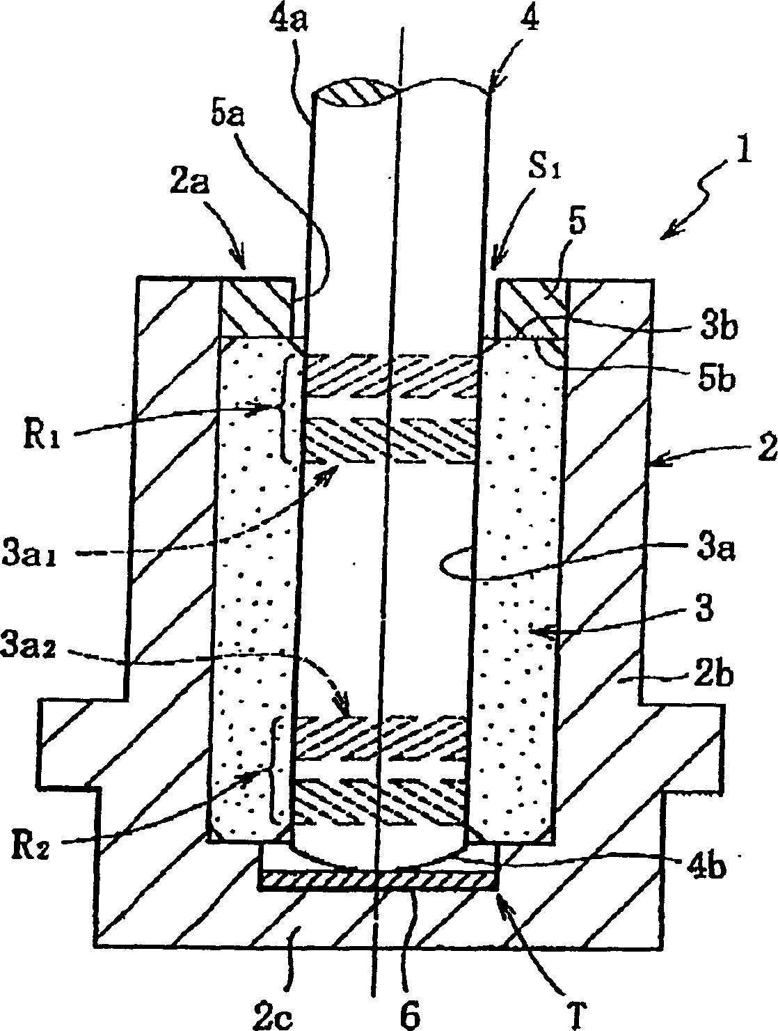
[0159] In the fluid bearing device 1 of the form shown in FIG. 1, lubricating oil is injected under the above-mentioned form (vacuum immersion oil), and by changing the vacuum degree in the vacuum chamber at that time, the inner space of the sleeve 2 after being opened under atmospheric pressure is manufactured. Five types of test bearing devices (Examples 1 to 2, Comparative Examples 1 to 3) with different amounts of residual air were produced. It is difficult to measure the amount of residual air in the inner space of the sleeve after vacuum oil immersion, but for example, if the vacuum degree in the vacuum tank is reduced to 380 Torr (1 / 2 of the atmospheric pressure), it can be estimated that it is open in the atmospheric pressure. 50vol% of the air in the inner space remains in the rear sleeve, so the residual air volume is calculated in this way.


PUM


Abstract

The present invention provides a fluid bearing device. The inner space of the shaft sleeve (2) sealed by the sealing member (5) contains the inner pores (porous tissue pores) of the bearing member (3), so that the air is not mixed and the body is lubricated with oil. Filled, the oil level of the lubricating oil is located in the sealed space S1. Under the reduced pressure of 100 Torr, even when the fluid bearing device (1) is arranged in any configuration such as upright configuration, upside down configuration, lateral placement configuration, and oblique configuration configuration, the lubricating oil does not leak to the outside of the sleeve (2).

Description

[0001] This application is a divisional application with the filing date being November 11, 2002, the application number being 02149300.6, and the title of the invention being "fluid bearing device". technical field [0002] The present invention relates to a fluid bearing device that supports a rotating part in a non-contact manner through an oil film generated in a radial bearing gap; the fluid bearing device is most suitable for use as information equipment such as disk devices such as HDD and FDD , CD-ROM, CD-R / RW, DVD-ROM / RAM and other optical disk devices, MD, MO and other optical-disk devices and other spindle motors, copiers, laser beam printers (LBP), barcode scanners and other scanning equipment motors, Or electrical equipment, such as small motors such as axial fans. Background technique [0003] The various motors mentioned above require high speed, low cost, and low noise in addition to high rotational accuracy. Among the major constituent factors in determinin...

Claims


Application Information

Patent Timeline
IPC IPC(8): F16C32/00
Inventor 栗村哲弥山本康裕川濑达夫
Owner NTN CORP
Why Eureka
Try Eureka