
Convection portion structure of convection electronic microwave oven

A microwave oven and electronic technology, which is applied in household stoves/stoves, electric heating fuel, household heating, etc., can solve the problems of rising manufacturing costs and increasing assembly processes, and achieve the effects of reducing manufacturing time and manufacturing costs and improving structure

Inactive Publication Date: 2006-05-31
LG ELECTRONICS (TIANJIN) APPLIANCES CO LTD
View PDF0 Cites 2 Cited by
  • Summary
  • Abstract
  • Description
  • Claims
  • Application Information

AI Technical Summary

Problems solved by technology

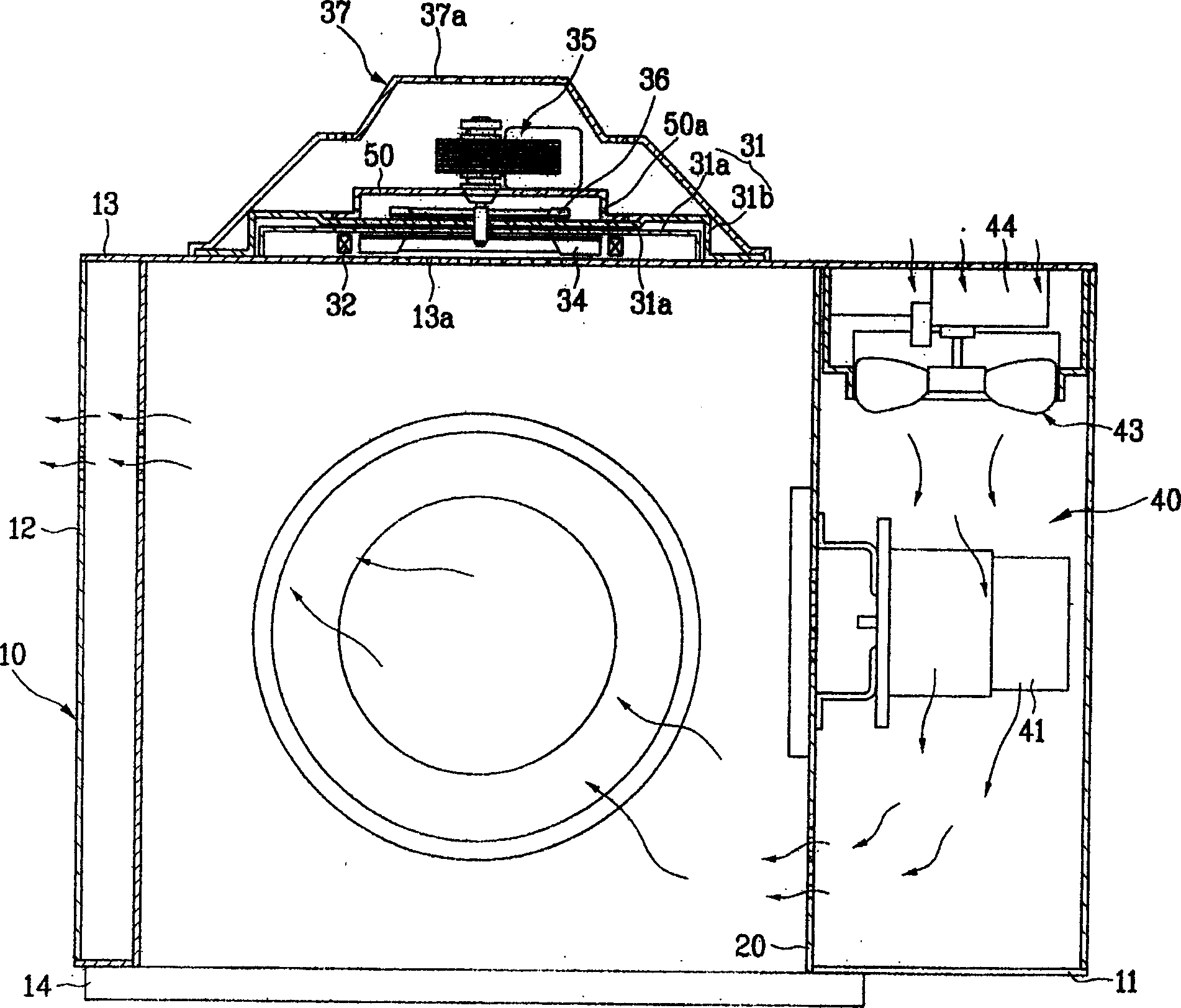
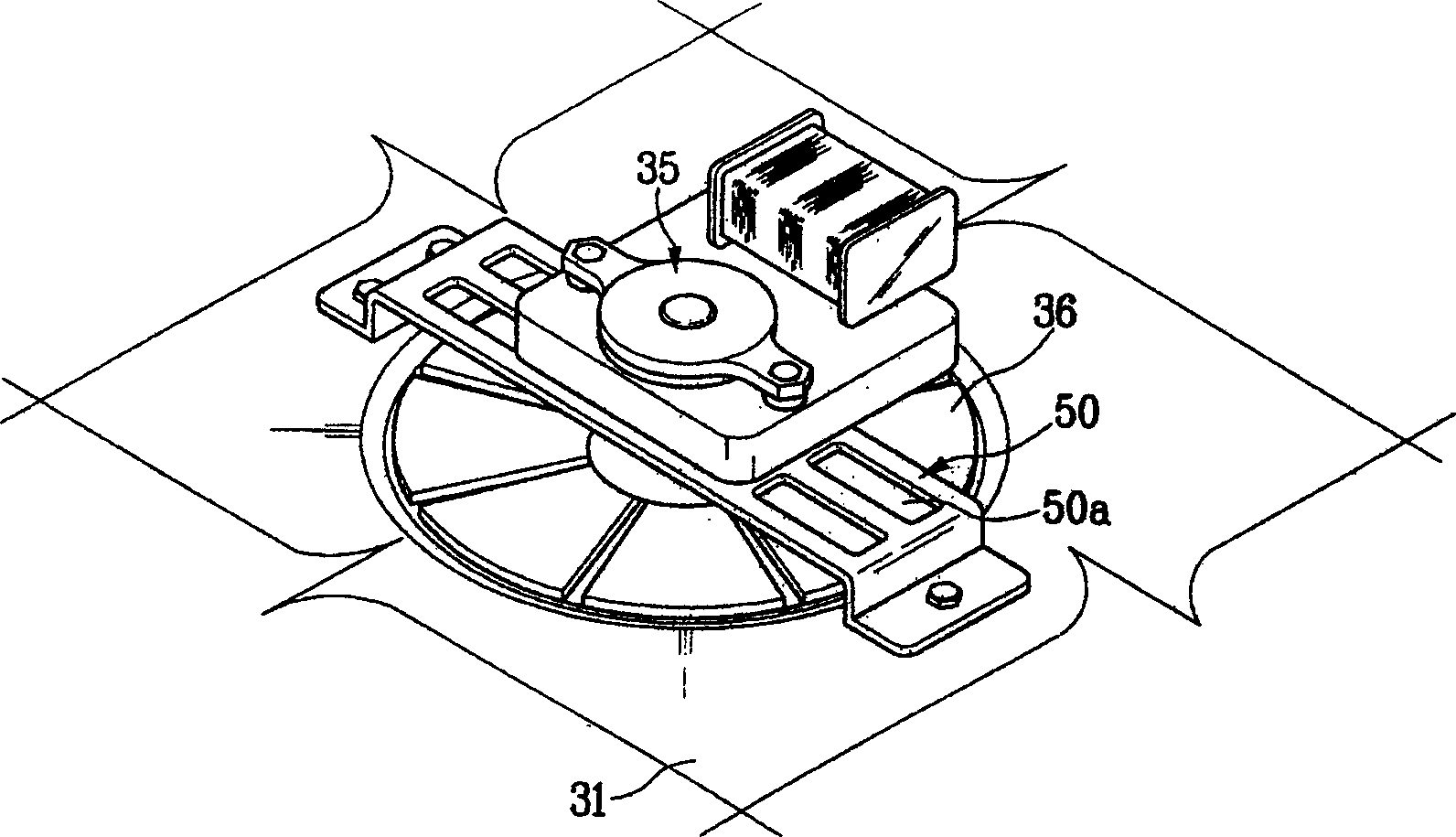
[0018] In order to ensure the rotational movement of the counterflow fan 36, the convection chamber electronic microwave oven of the prior art uses an additional bracket to fix the convection chamber motor 35, resulting in an increase in the overall manufacturing cost and increasing the corresponding assembly process

Method used


Image

  • Convection portion structure of convection electronic microwave oven
  • Convection portion structure of convection electronic microwave oven
  • Convection portion structure of convection electronic microwave oven

Examples


Embodiment Construction

[0040] Embodiments of the present invention will be further described below in conjunction with the accompanying drawings.

[0041] In the following description, the parts that have the same structure as those of the conventional convection microwave oven use the same numbers, and the detailed description is omitted here.

[0042] Figure 4 It is a horizontal cross-sectional view of a preferred embodiment of the internal structure of the convection microwave oven of the present invention.

[0043] Such as Figure 4 As shown, the convection type electronic microwave oven in the preferred embodiment of the present invention mainly includes: a microwave oven body 10, a cavity 20, an electronic accessory chamber 40, and a convection part.

[0044] The microwave oven body 10 forms the appearance of the microwave oven, and consists of a front panel 11 forming the front side of the microwave oven, a shell 12 forming the two sides and the upper side of the microwave oven, and a rear...


PUM


Abstract

There is disclosed a convection part structure of a convection-type electronic microwave oven, which comprises a oven body, a cavity, an electronic fitting chamber and a convection part. A motor of the convection chamber electric machine fixed in the external convection chamber and combined with the convection fan to drive the fan. A countercurrent fan disposed between the internal convection chamber and the external convection chamber for radiating the heat produced by the motor of the convection chamber. A convection chamber cover is disposed on the back side of the convection chamber for protecting the convection chamber and the members inside.

Description

technical field [0001] The invention relates to an electronic microwave oven, in particular to a convection part structure of a convection type electronic microwave oven with a convection function. Background technique [0002] Generally speaking, electronic microwave ovens use high-frequency waves of about 2,450 MHz per second as a heating source to disrupt the arrangement of food molecules, and use the heat generated by intermolecular friction to cook food. [0003] Refer below figure 1 and figure 2 An existing convection chamber electric microwave oven is described. [0004] Such as figure 1 As shown, the existing convection microwave oven includes: a microwave oven body 10 consisting of a front panel 11, a casing 12 and a rear panel 13; a cavity 20 forming a cooking chamber 21; an electronic accessory chamber 40 provided with various electronic components. [0005] A chamber door 14 for opening and closing the interior of the chamber 20 is installed on the front pan...

Claims


Application Information

Patent Timeline
IPC IPC(8): F24C7/02
Inventor 辛文寿陈再明
Owner LG ELECTRONICS (TIANJIN) APPLIANCES CO LTD
Learn More