
Rear body structure of vehicle

A car body structure and vehicle rear technology, applied in the direction of superstructure, vehicle parts, superstructure sub-assembly, etc., can solve the problems such as inability to obtain connection stiffness, achieve weight and cost reduction of car body, reduce wall thickness, reduce Effect of Part Quantity

Active Publication Date: 2006-05-17
MITSUBISHI MOTORS CORP
View PDF1 Cites 19 Cited by
  • Summary
  • Abstract
  • Description
  • Claims
  • Application Information

AI Technical Summary

Problems solved by technology

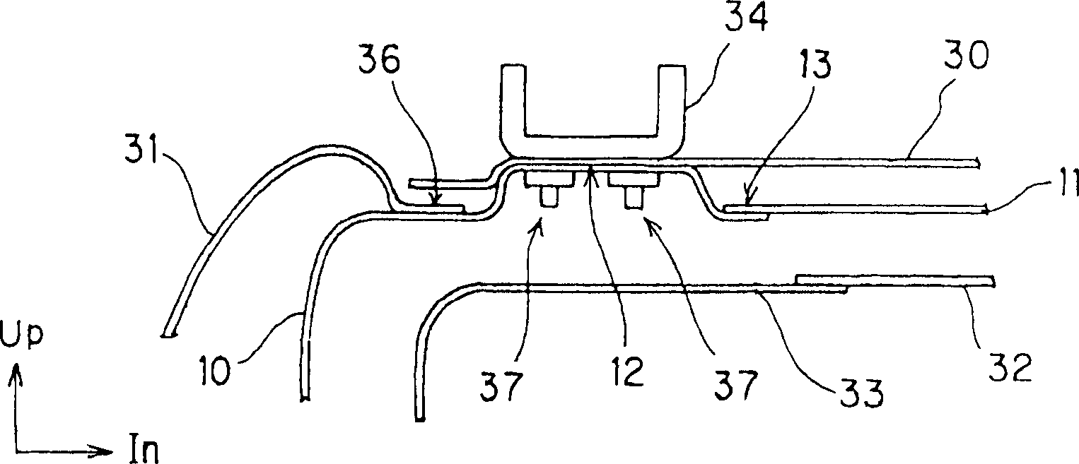
However, if Figure 4 As shown, the three components have been connected together by welding in this area. If another component is welded here, considering the performance of the welded connection, it may not be possible to obtain sufficient connection stiffness.

Method used


Image

  • Rear body structure of vehicle
  • Rear body structure of vehicle
  • Rear body structure of vehicle

Examples


Embodiment Construction

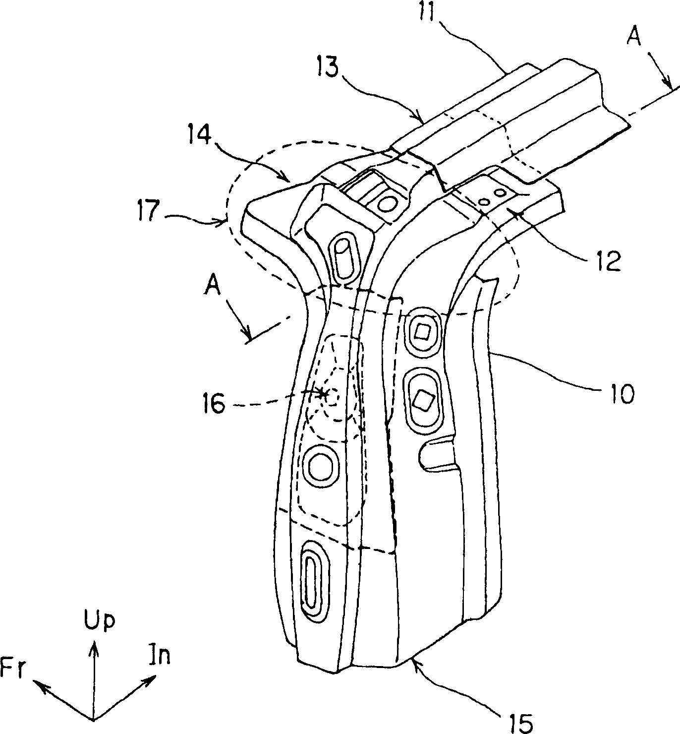
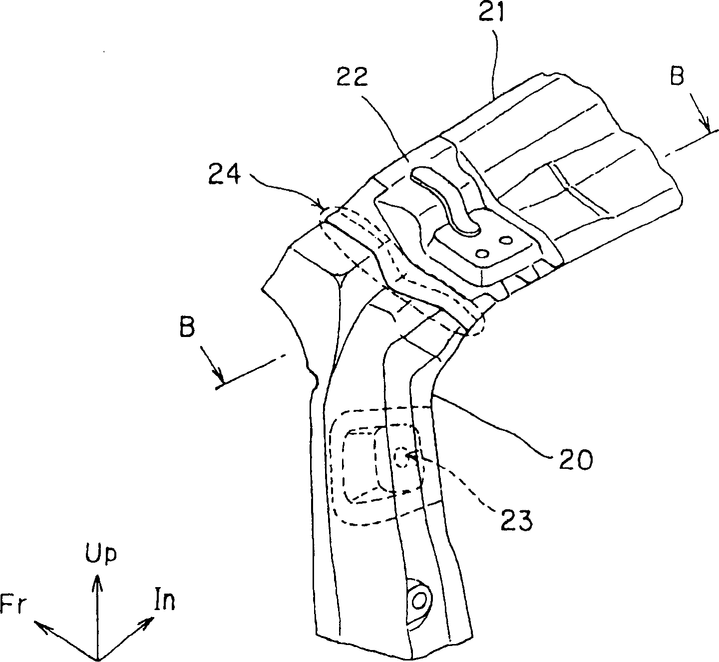
[0021] Below, refer to Figure 1 to Figure 5 , the structure of the rear body of the vehicle will be described. figure 1 It is a perspective view of a vehicle rear body structure according to an embodiment of the present invention. figure 2 It is a perspective view of a conventional vehicle rear body structure. image 3 yes figure 1 A cross-sectional view of the vehicle rear body structure of the embodiment of the present invention along line A-A. Figure 4 yes figure 2 A sectional view of the rear body structure of a conventional vehicle along line B-B in . Figure 5 It is a perspective view of the rear body structure of the vehicle. Front (Fr), inner (In) and upper (Up) arrows in the figure indicate the front of the vehicle, the inner side in the vehicle width direction, and the upper side of the vehicle, respectively.

[0022] Such as figure 1 As shown, the door pillar reinforcement 10 is formed into a substantially Y shape so that it can be connected with the re...


PUM


Abstract

The invention discloses a corner structure located above the tailgate of a vehicle. It includes: a roof panel, which constitutes the roof; a rear roof outer beam, which is arranged at the rear of the roof panel inside the compartment and extends along the width direction of the vehicle; a rear roof inner beam, which is connected to the rear roof outer beam and is connected with it A closed combined shape is formed; the door post reinforcement is integrally installed with the tailgate hinge reinforcement member on its outer side; the inner corner extension part is connected with the door post reinforcement and forms a closed combined shape with it.

Description

technical field [0001] The present invention relates to a rear body structure of a vehicle. Background technique [0002] Such as Figure 5 As shown, the corner position 50 (hereinafter referred to as the corner position 50) above the tailgate of the vehicle is as follows in the prior art figure 2 shown. exist figure 2 Among them, the upper end of the tailgate pillar reinforcement 20 along the inner side of the vehicle width is connected to the rear roof outer cross member 21 by welding. Moreover, in the corner portion 50, except that the tailgate pillar reinforcement 20 and the rear roof outer beam 21 are connected by welding, the upper end portion of the outer side panel 41 (see Figure 4 ) is also connected by welding. Figure 4 means along the figure 2 A cross-sectional view of line B-B in . [0003] Such as Figure 4 As shown, the tailgate hinge 44 on which the tailgate 51 is mounted is mounted on the rear roof outer cross member 21 . However, it is dangerous...

Claims


Application Information

Patent Timeline
IPC IPC(8): B62D25/08
Inventor 岛村昌志
Owner MITSUBISHI MOTORS CORP
Learn More