Super-small size switch

An ultra-small, switching technology, applied in electrical switches, electrical components, preventing/interrupting contact welding, etc., can solve the problem of expensive production and installation, and achieve the effect of simple solution

Inactive Publication Date: 2006-05-10
CHAFA FRIEDRICH SCHAFFEN CO LTD
View PDF2 Cites 9 Cited by
  • Summary
  • Abstract
  • Description
  • Claims
  • Application Information

AI Technical Summary

Problems solved by technology

However, due to the provision of such additional components, it is very expensive both in production and in installation.

Method used


Image

  • Super-small size switch
  • Super-small size switch
  • Super-small size switch

Examples


Embodiment Construction

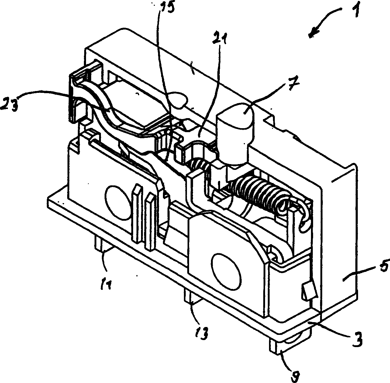
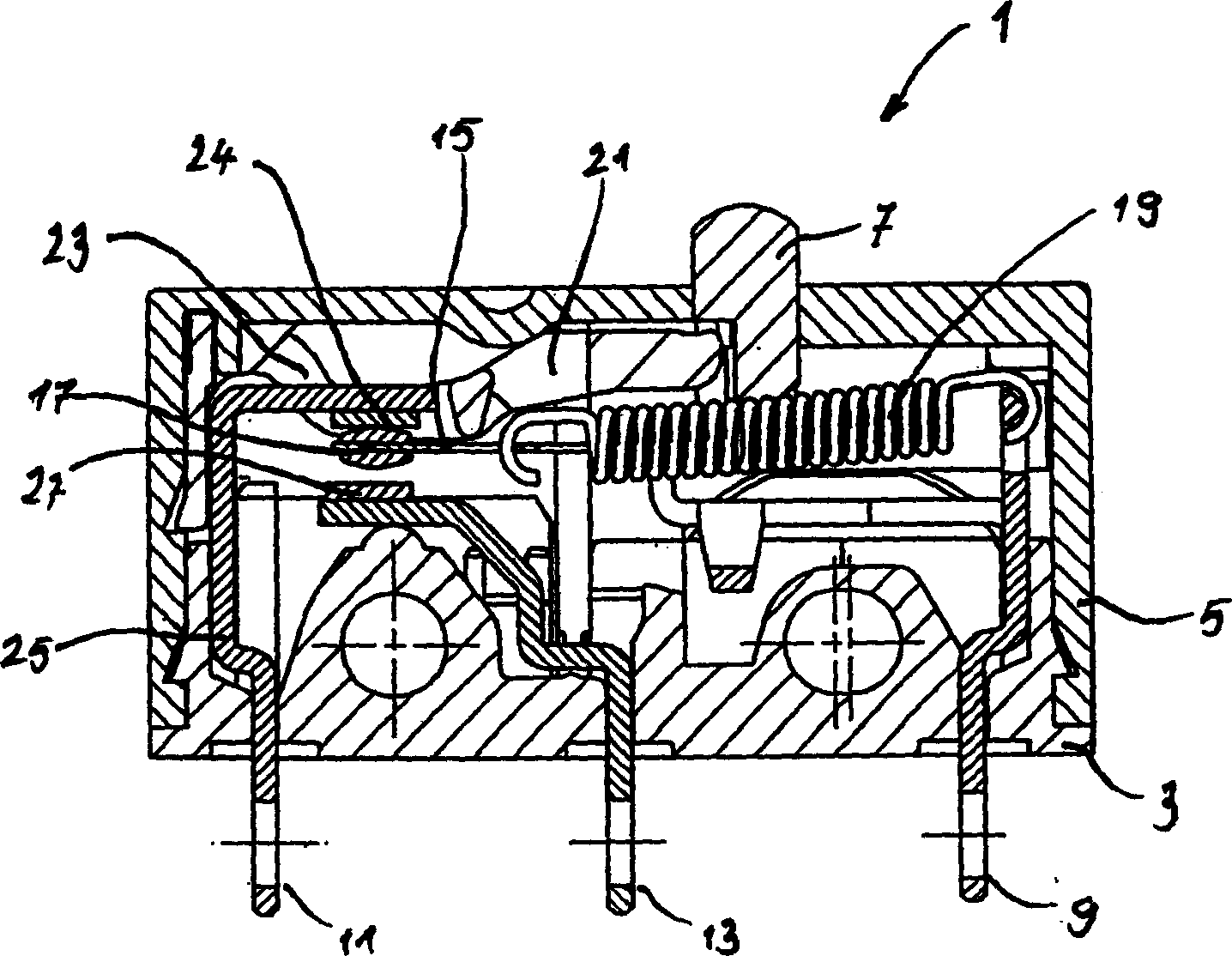
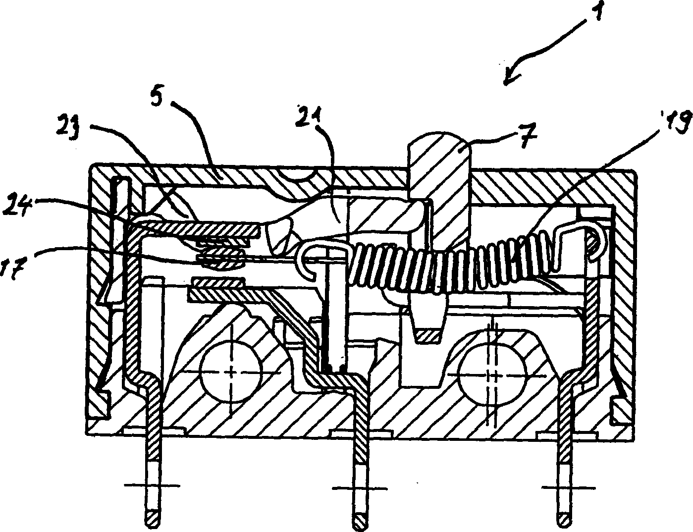
[0027] exist figure 1 The subminiature switch 1 is shown in a perspective view, wherein the upper operating element 7 and the lower lugs or connection contacts 9 , 11 and 13 can be seen. The structure is supported on a seat 3 of a housing, out of which the connection contacts 9, 11 and 13 protrude downwards. Only one half of the housing is shown in the figure.

[0028] In this configuration of the microswitch, the actuating element is not arranged centrally, but is, for example, offset to the right. The operating member 7 pushes via a tension spring 19 against a contactor 15 which is movably (for example rotatably) arranged and has two contacts at its movable end. The blades of the contactor 15 are electrically conductively connected to the common connecting contact 9 via a contact bearing (not shown in the figure). Contact 17 forms a contact point with fixed contacts 24 and 27 . The upper fixed contact 24 is electrically conductively connected to the connecting contact 11...


PUM


Abstract

The switch has an actuator (7) arranged relative to center of a housing base and cover. Terminal contacts (11, 13) are electrically connected with fixed contacts. A contactor (15) is held in one of switch positions by a bi-stable spring arrangement in dependence of the switch position of the actuator. A disconnector (21) is moved by the actuator (7) towards the contact position of the fixed contacts and the contactor.

Description

technical field [0001] The invention relates to an ultra-small switch. Background technique [0002] A prior art microswitch is disclosed in EP618603B1 and GB2142471A, wherein the microswitch has a housing with a cover, an operating element protruding from the housing and external connection contacts. The operating part is arranged at a position deviated from the middle of the casing. The connection contacts are electrically conductively connected to fixed contacts located inside the housing. A movably arranged, in particular rotatably arranged, contactor can assume two positions depending on the actuating position. In the first and second switching position the contactor is each held by a bistable spring arrangement (tension spring). [0003] An additional component, a pressure device or a separator or an auxiliary operating element, is arranged in the housing, said additional component being pressed by the operating element when switching from the first switching positi...

Claims


Application Information

Patent Timeline
Patent Type & Authority Applications(China)
IPC IPC(8): H01H13/20
CPCH01H3/001H01H13/14H01H13/28
Inventor 托马斯·朔贝尔斯特凡·赖因德尔
Owner CHAFA FRIEDRICH SCHAFFEN CO LTD
Why Eureka
Try Eureka