Gearing reducer made of magnesium alloy for electric children vehicle, and art for commercialized prodn. of same
A technology of gear reduction box and electric baby carriage, which is applied in the direction of vehicle gearbox, vehicle parts, wheel transmission device, etc., can solve the problems that electric baby carriage cannot be used normally, the reduction box cannot work normally, and the mold manufacturing cost is high, and the structure is simple. , the effect of saving heating energy consumption and simple manufacturing process
- Summary
- Abstract
- Description
- Claims
- Application Information
AI Technical Summary
Problems solved by technology
Method used
Image
Examples
specific Embodiment approach 1
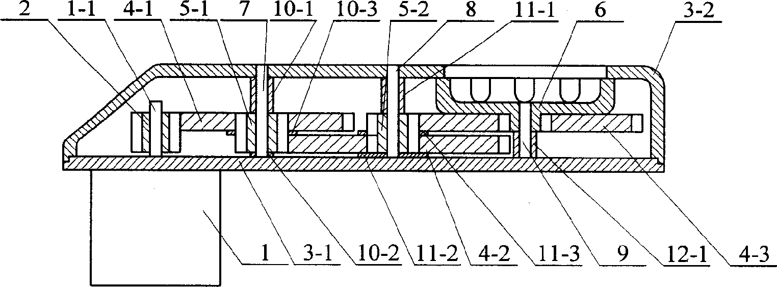
[0006] Specific implementation mode one: combine figure 1 Describe this embodiment, the magnesium alloy gear reduction box of the electric stroller of this embodiment is composed of a housing composed of a base 3-1 and an outer cover 3-2, a motor 1, a main transmission gear 2, a thin gear, a thick gear, a gear shaft 6, a second A shaft 7, a second shaft 8, a third shaft 9, a first positioning device, a second positioning device, and a third positioning device; the thin gear is composed of a first thin gear 4-1, a second thin gear 4- 2. The third thin gear 4-3; the thick gear is composed of the first thick gear 5-1 and the second thick gear 5-2; the motor 1 is fixed on the outer panel of the base 3-1 of the housing, The output shaft 1-1 of the motor 1 is installed in the casing, the output shaft 1-1 of the motor 1 is equipped with the main transmission gear 2, the main transmission gear 2 meshes with the outer ring gear of the first thin gear 4-1, and the first thin gear 4-1 i...
specific Embodiment approach 2
[0008] Specific implementation mode two: combination figure 1 Describe this embodiment, the first positioning device of this embodiment is made up of first positioning sleeve 10-1, first positioning pad 10-2, second positioning pad 10-3; The first positioning sleeve 10-1 is installed on the first shaft 7 between the gears 5-1, and the first positioning pad 10 is installed on the first shaft 7 between the base 3-1 of the housing and the first thick gear 5-1. -2, the first thick gear 5-1 between the first thin gear 4-1 and the second thin gear 4-2 is equipped with a second positioning pad 10-3. Using the sawn metal tube as the first positioning sleeve 10-1 and cooperating with the first positioning pad 10-2 and the second positioning pad 10-3 (using standard washers) can realize the fast positioning of the first thick gear 5-1. Axial positioning. Other components and connections are the same as those in the first embodiment.
specific Embodiment approach 3
[0009] Specific implementation mode three: combination figure 1 Describe this embodiment, the second positioning device of this embodiment is made up of second positioning sleeve 11-1, third positioning pad 11-2, fourth positioning pad 11-3; A second positioning sleeve 11-1 is installed on the second shaft 8 between the gears 5-2, and a third positioning pad 11 is installed on the second shaft 8 between the base 3-1 of the housing and the second thick gear 5-2. -2, the second thick gear 5-2 between the second thin gear 4-2 and the third thin gear 4-3 is equipped with a fourth positioning pad 11-3. Adopt the sawn metal tube as the second positioning sleeve 11-1 and cooperate with the third positioning pad 11-2 and the fourth positioning pad 11-3 (using standard washers) to realize the rapid operation of the second thick gear 5-2. Axial positioning. Other compositions and connections are the same as in the specific embodiment.
PUM
 Abstract
Description
Claims
Application Information
 - R&D
- Intellectual Property
- Life Sciences
- Materials
- Tech Scout
- Unparalleled Data Quality
- Higher Quality Content
- 60% Fewer Hallucinations
Browse by: Latest US Patents, China's latest patents, Technical Efficacy Thesaurus, Application Domain, Technology Topic, Popular Technical Reports.
© 2025 PatSnap. All rights reserved.Legal|Privacy policy|Modern Slavery Act Transparency Statement|Sitemap|About US| Contact US: help@patsnap.com


