Automobile top structure

A technology for automobiles and roofs, which is applied to the superstructure, superstructure sub-assemblies, motor vehicles, etc., can solve the problems of reduced interior space, increased cost and weight, etc., and achieves spacious interior space, reduced cost and weight. , to ensure the effect of the interior space

Active Publication Date: 2006-04-05
ISUZU MOTORS LTD
View PDF1 Cites 5 Cited by
  • Summary
  • Abstract
  • Description
  • Claims
  • Application Information

AI Technical Summary

Problems solved by technology

That is, the arc arch of the roof is erected between the left and right upper side beams, which is easy to increase in size
In addition, as the top plate moves upward from the top of the side beams, the bending portion of the roof arch becomes longer, which makes the roof arch larger.
As such, the increase in the size of the arc arch of the roof will increase the cost and weight
[0006] In addition, since the bent portion of the roof arch protrudes from the inner side of the wall portion bent downward from both sides of the roof in the vehicle width direction, the Reduced cabin interior space on both sides in the vehicle width direction

Method used


Image

  • Automobile top structure
  • Automobile top structure
  • Automobile top structure

Examples


Embodiment Construction

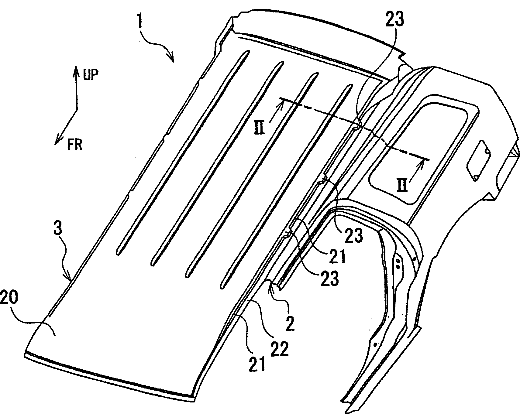
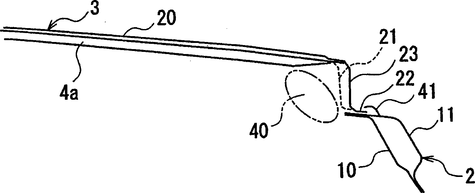
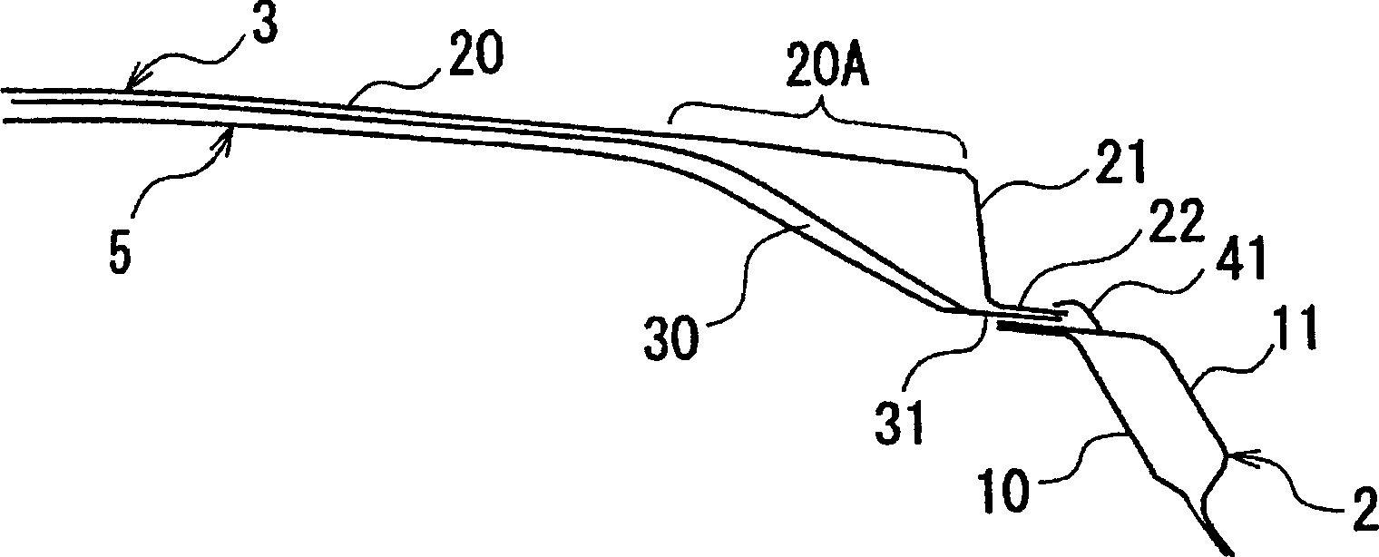
[0023] Next, an embodiment of the present invention will be described with reference to the accompanying drawings. figure 1 In order to show the perspective view of the state where the side roof rail and the roof panel are joined in this embodiment, figure 2 for figure 1 Section view of II-II view, image 3 It is an enlarged cross-sectional view of the main part of the top cover structure of the comparative example, Figure 4 for figure 1 An enlarged perspective view of the main part of the ceiling wall of Figure 5 To show the roof arches are configured in figure 1 An enlarged top view of the main part of the state on the top plate. In addition, FR and UP in the figure represent the front of the vehicle and the upper side of the vehicle, respectively.

[0024] like figure 1 and figure 2 As shown, the vehicle 1 of this embodiment has: side roof rails 2 extending in the vehicle front-rear direction on both sides of the vehicle width direction, a roof panel 3 placed on...


PUM


Abstract

To provide a roof structure for an automobile capable of reducing the cost and weight of a roof bow, and securing a large cabin space. The roof bow 4 is joined only to the roof part 20 of a roof panel 3. That is, it is not necessary to provide a part bent along the inner face of the wall part 21 of the roof panel 3 and joined to a side roof rail 2 in the roof bow 4, therefore, the roof bow 4 can be miniaturized. Furthermore, a protruded part 23 nearly in a projecting shape is formed in the wall part 21 of the roof panel 3. Thus, strength insufficient in a structure where the roof bow 4 is joined only to the roof part 20 of the roof panel 3 is compensated, and strength equivalent to a case where the roof bow is joined to the side roof rail 2 can be secured. Moreover, the protruded part 23 formed in the wall part 21 of the roof panel 3 is protruded to the outside in the vehicle width direction, and thus, a space continued along the vehicle longitudinal direction is formed in an area on the inner face of the wall part 21 of the roof panel 3.

Description

technical field [0001] The invention relates to a roof structure of an automobile. Background technique [0002] There is known a roof structure for an automobile in which a plurality of roof arches are arranged below the roof panel, and roof rails on opposite sides are placed and joined to the roof panel and the roof arches. [0003] [Patent Document 1] Japanese Patent Laid-Open No. 2000-318644 [0004] However, when the volume of the passenger compartment space is increased in the height direction, in the above-mentioned roof structure, the roof plate is separated and bulged upward from the upper surface of the side roof side sills extending in the vehicle front-rear direction on both sides in the vehicle width direction. In addition, on the underside of the roof, a plurality of roof arches extending in the vehicle width direction are arranged at predetermined positions in the front and rear of the vehicle, thereby reinforcing the roof and ensuring the necessary vibration...

Claims


Application Information

Patent Timeline
IPC IPC(8): B62D25/00B62D65/02
Inventor 石神健夫
Owner ISUZU MOTORS LTD
Why Eureka
Try Eureka