
Planer with improved chip removal

A technology of planer and shavings, which is applied in the field of shaving discharge channels, and can solve problems such as shavings falling off, blocking observation of workpieces, and blocking channels

Inactive Publication Date: 2006-03-29
ROBERT BOSCH GMBH
View PDF0 Cites 3 Cited by
  • Summary
  • Abstract
  • Description
  • Claims
  • Application Information

AI Technical Summary

Problems solved by technology

Due to the change in direction, the shavings end up easily detached from the airflow and block the passage
[0004] Another disadvantage of this structure of the prior art is that the shavings discharge pipe or collection container is arranged on the side of the planer
This blocks viewing artifacts

Method used


Image

  • Planer with improved chip removal
  • Planer with improved chip removal
  • Planer with improved chip removal

Examples


Embodiment Construction

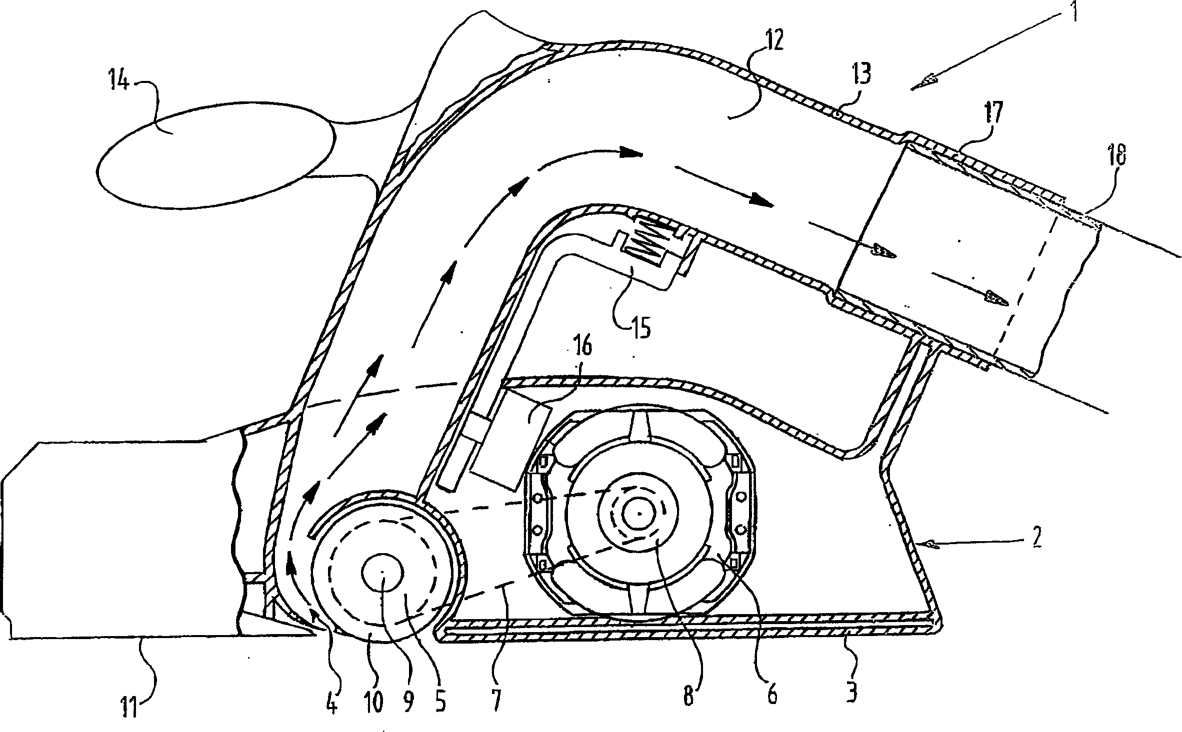
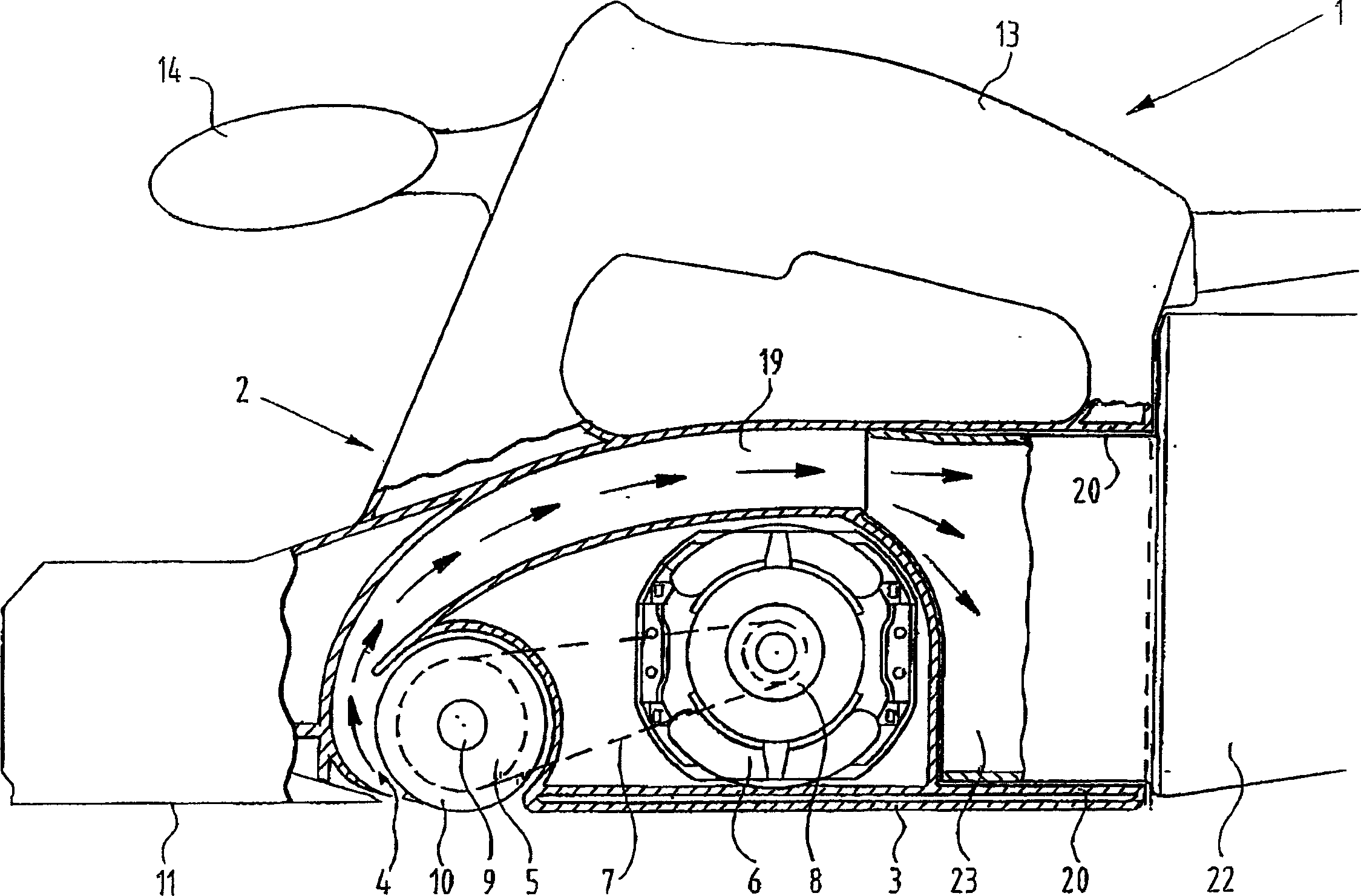
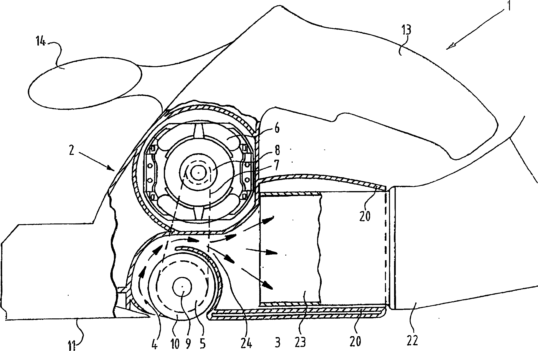
[0019] figure 1 The longitudinal cross-sectional form of the planer as a whole indicated by reference numeral 1 is shown. The planer includes a housing 2 provided with a base plate 3. At the front of the substrate in the moving direction, the planer knife roll cavity 4 provided with the planer knife roll 5 is recessed into the housing. The planer knife roll 5 is mounted via a shaft 9 supported by a bearing not shown in the figure. The planer knife roller holder is driven by an electric motor 6 arranged in the housing via a toothed belt 7 which surrounds a pulley 8 arranged on the motor shaft and a pulley 10 arranged on the planer knife roller shaft.

[0020] The adjustable base 11 is provided at the front of the housing. The mechanism for adjusting the base is not shown because it is not important to the invention.

[0021] The above-mentioned elements can be found in planers of the prior art.

[0022] The present invention provides an arrangement in which the shavings discharge...


PUM


Abstract

The present invention provides a planer, comprising: (a) a housing (2); (b) a motor (6) arranged in the housing; (c) a planer knife roller cavity (4) arranged in the housing; (d) a planer knife roller (5) arranged in the planer knife roller cavity and coupled for driving to the motor; (e) a shavings removal channel (12) extending in the housing from the planer knife roller cavity, characterized in that the shavings removal channel extends over its whole path with a directional component in the direction of movement of the planer.

Description

Technical field [0001] The invention relates to a planer, comprising a housing, a motor arranged in the housing, a planer knife roller cavity arranged in the housing, a planer knife roller arranged in the cavity of the planer knife roller and connected to the motor for driving, and The shavings discharge channel extending from the cavity of the planer knife roll in the housing. Background technique [0002] These planers are well known. [0003] In these planers, the shavings discharge channel includes a portion that extends tangentially and is connected to a portion extending in the axial direction of the planer knife roll. In most planers, the motor is located behind the planer knife roll. The connection of the tangential part and the axial part of the channel changes the direction of the air flow including the shavings, which reduces the efficiency of shavings discharge. Due to the change of direction, the shavings are easily separated from the airflow and block the passage. ...

Claims


Application Information

Patent Timeline
Patent Type & Authority Applications(China)
IPC IPC(8): B27C1/10B23Q11/00
CPCB23Q11/0042B27C1/10
Inventor P·旺宁克霍夫
Owner ROBERT BOSCH GMBH
Learn More