Low power consumption digital controlled contact device and control system thereof

A low-power, contactor technology, applied in relays, electromagnetic relays, electromagnetic relay details, etc., can solve the problems of restricting the application and development of control systems, poor motion controllability, short service life, etc., and achieve flexible and convenient line connection. , Significant energy saving effect, long service life effect

Inactive Publication Date: 2006-03-29
刘津平 +1
View PDF0 Cites 6 Cited by
  • Summary
  • Abstract
  • Description
  • Claims
  • Application Information

AI Technical Summary

Problems solved by technology

The main disadvantages of the prior art AC contactors are: poor controllability of movement, large driving power, high energy consumption, easy to cause coil burnout, and short service life; the driving device of the new intelligent contactor is equipped with advanced electronic circuits And the control chip, real-time control of the entire dynamic process, so that its performance has been improved, but there are still problems such as complex drive circuit and high starting power
The control system with AC contactor as the main body has the characteristics of simple control circuit, strong driving force and low cost. When a programmable logic control device (PLC) drives a large AC contactor, it needs to be amplified in the middle stage to realize it. It is necessary to design a special control circuit to reduce the power consumption during pull-in, which restricts the application and development of the control system

Method used


Image

  • Low power consumption digital controlled contact device and control system thereof
  • Low power consumption digital controlled contact device and control system thereof
  • Low power consumption digital controlled contact device and control system thereof

Examples


Embodiment 1

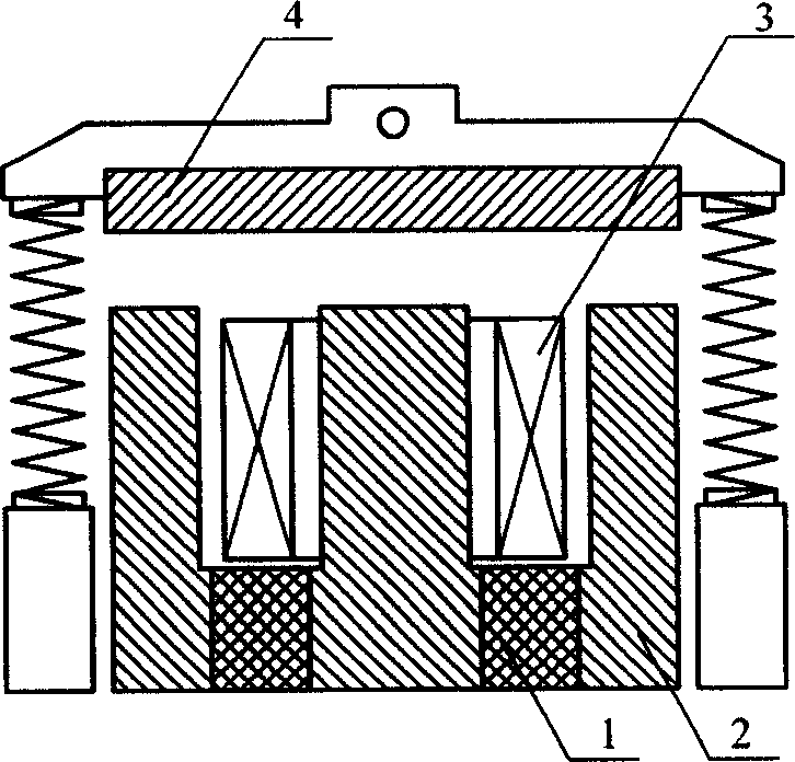
[0036] figure 1 A schematic diagram of an EI core structure is shown. In the figure, 1 is a permanent magnet; 2 is a static iron core; 3 is an excitation coil; 4 is a moving iron core. The static iron core 2 is an E-shaped structure, and the moving iron core 4 is an I-shaped structure. In this example, the core of the low-power CNC contactor is made of silicon steel sheets, such as figure 2 shown. The permanent magnet 1 is an NdFeB permanent magnet, and this example adopts a double permanent magnet structure. The permanent magnet 1 is embedded in the middle position of the groove bottom of the E-type static iron core 2 . The permanent magnet 1 is embedded in this position for processing and installation, and the mechanical strength of the static iron core will not be affected too much due to the processing of the static iron core and the installation of the permanent magnet. When in the disconnected state, the reluctance of each branch from the position of the permanent ...

Embodiment 2

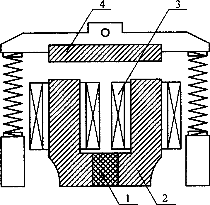
[0038] Such as image 3 As shown, the iron core structure of this example is UI-shaped, the static iron core 2 is a U-shaped structure, and the moving iron core 4 is an I-shaped structure. The permanent magnet 1 is embedded in the middle of the groove bottom of the U-shaped static iron core 2, Figure 4A transverse sectional view of the static core of this example is shown. This low-power digitally controlled contactor uses dual field coils. The UI-type core is suitable for large-scale low-power CNC contactors of 300-800A. The single permanent magnet structure in this example simplifies the design of the magnetic circuit. Parallel drive or synchronous drive of double excitation coils can effectively solve the problem of difficult start of large contactors when the nominal voltage DC24V is used, highlighting the superiority of its structure. Other structural features of this example are the same as in Example 1.

Embodiment 3

[0040] Figure 5 The schematic diagram of the driving circuit of this example is shown. The driving circuit is installed in the base of the low-power numerical control contactor, and forms a whole with the low-power numerical control contactor. Figure 5 Among them, the excitation coil KM is connected to the power supply through the transfer switch JK2 and the transfer switch JK3. The transfer switch JK2 is the contact of the relay J2, and the transfer switch JK3 is the contact of the relay J3. The charge and discharge of capacitor C5 and capacitor C6 connected in series with relay J2 and relay J3 are controlled by switch JK1-1 and switch JK1-2, and switch JK1-1 and switch JK1-2 are controlled by relay J1, and relay J1 is controlled by an external control signal. image 3 C is connected to the external control signal, Vcc is connected to the external positive power supply, and G is the common ground.

[0041] Figure 5 The medium power supply circuit has three relatively i...


PUM


Abstract

The invention relates to a switching device, especially a contactor iron core and a contactor drive circuit. The invention overcomes the disadvantages of high driving power, high energy consumption and short service life in existing contactors, providing a low-power digital controlled contactor with built-in drive circuit and control port. The low-power digital controlled contactor comprises excitation coil, and dynamic and static iron cores, where the static iron core is stacked of silicon steel sheets and inserted with permanent magnet; the built-in drive circuit is connected with the excitation coil and used for driving the excitation coil by connecting external power supply and control signal. And the invention also provides a control system composed of the low-power digital controlled contactor. The invention has the beneficial effects of: low power consumption, easily driving, long service life, and being able to directly adopt nominal DC24V switching power supply to supply power, as well as remarkable energy saving effect.

Description

technical field [0001] The invention relates to a switch device, in particular to a contactor iron core and a contactor drive circuit. Background technique [0002] Since the AC contactor came into the market, it has been widely used in the two fields of industrial process control automation and low-voltage terminal power supply, and has a solid market foundation. The pull-in, hold-off, and break-off process of the AC contactor is a dynamic process with very complicated changing rules. The main disadvantages of the prior art AC contactors are: poor controllability of movement, large driving power, high energy consumption, easy to cause coil burnout, and short service life; the driving device of the new intelligent contactor is equipped with advanced electronic circuits And the control chip, real-time control of the entire dynamic process, so that its performance has been improved, but there are still problems such as complex drive circuit and high starting power. The contr...

Claims


Application Information

Patent Timeline
Patent Type & Authority Applications(China)
IPC IPC(8): H01H51/00H01H47/02
CPCH01H47/04H01H47/02H01H51/01H01H50/36H01H51/2209
Inventor 刘津平陈荣高
Owner 刘津平
Why Eureka
Try Eureka