
Tunnelling resonance microsound sensor

An acoustic sensor and resonance tunneling technology, applied in the sensor field, can solve the problems of inability to meet high-precision requirements, low sensitivity, poor temperature stability, etc., and achieve the effects of low cost, good temperature stability, and improved sensitivity

Inactive Publication Date: 2006-03-15
ZHONGBEI UNIV
View PDF0 Cites 4 Cited by
  • Summary
  • Abstract
  • Description
  • Claims
  • Application Information

AI Technical Summary

Problems solved by technology

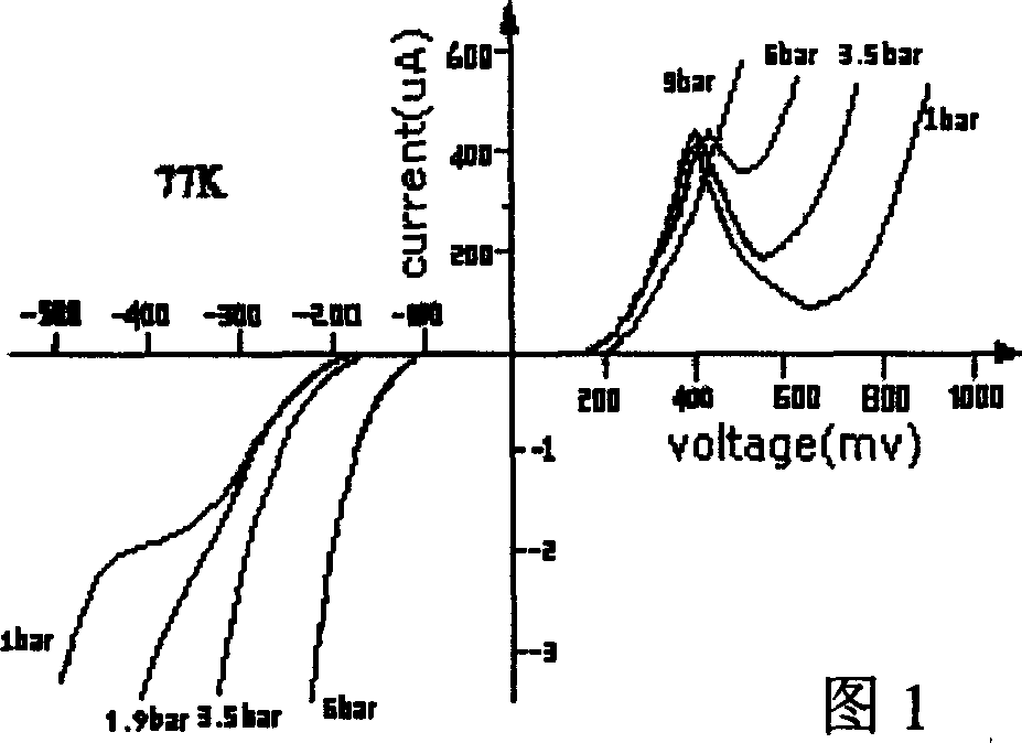
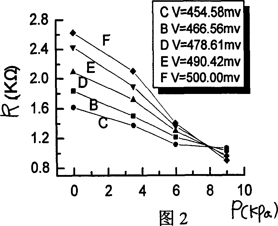
[0009] The invention solves the problem that the piezoresistors of the existing silicon piezoresistive acoustic sensors are all doped polysilicon, which has low sensitivity and poor temperature stability, and cannot meet the high-precision requirements of modern testing technology. The thin film has the characteristics of high sensitivity piezoresistive effect, providing a high sensitivity resonant tunneling microacoustic sensor

Method used


Image

  • Tunnelling resonance microsound sensor
  • Tunnelling resonance microsound sensor
  • Tunnelling resonance microsound sensor

Examples


Embodiment Construction

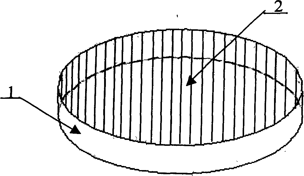
[0031] The resonant tunneling microacoustic sensor is made by the following method: the required superlattice film 2 is grown on the semiconductor substrate 1 by molecular beam epitaxy (MBE) technology, and the microelectromechanical device (MEMS) processing technology is used to Do the following processing:

[0032](1) Utilize the etching process to remove all the thin films on the substrate 1 except the four thin films distributed in the shape of "ten" (such as Figure 4 as shown in a);

[0033] (2) Using an etching process, each remaining film ( Figure 4 b) The rest of the area except the strip area is etched to the electrode contact layer 3 of the collector, so that a convex line is formed on each film ( Figure 4 c);

[0034] (3) Deposit the ohmic contact layer on the surface of the film by the deposition method, and then use the lift-off method to make the collector electrode 4 and the emitter electrode 7 ( Figure 4 d) (The emitter does not need to be stripped); th...


PUM


Abstract

A resonant tunneling micro sound transducer is prepared as fabricating out resonant tunneling piezo ¿C resistance on super lattice film, fabricating super lattice film substrate to be force transmission structure of indent resonant cavity and setting four resonant tunneling piezo ¿C resistances on edge of indent resonant cavity. The said transducer is actually a quantum component prepared by MEMS process.

Description

technical field [0001] The invention relates to a sensor, in particular to an acoustic sensor, in particular to a high-sensitivity resonant tunneling micro-acoustic sensor based on the piezoresistive effect of a superlattice film. Background technique [0002] At present, the piezoresistive acoustic sensor is a commonly used acoustic signal measurement device, which is based on the silicon piezoresistive effect principle. The so-called piezoresistive effect, that is, the solid under the action of the stress field, causes the change of the resistivity, thus causing the change of the resistance value. The piezoresistors of the existing silicon piezoresistive acoustic sensors on the market are all doped polysilicon, which has low sensitivity and poor temperature stability, and cannot meet the high precision requirements of modern testing technology. The existing smaller micro-acoustic sensors are mainly capacitive electret sensors; currently the smallest acoustic sensor is abo...

Claims


Application Information

Patent Timeline
IPC IPC(8): G01H11/08G01H11/06
Inventor 张文栋刘俊熊继军薛晨阳张斌珍谢斌桑胜波王建陈建军
Owner ZHONGBEI UNIV
Learn More