Eureka AIR delivers breakthrough ideas for toughest innovation challenges, trusted by R&D personnel around the world.

Air conditioner

A technology for air-conditioning equipment and rooms, which is applied in the field of air-conditioning equipment and its operation, and can solve the problems that the dehumidification capacity cannot be fully achieved, and the air temperature and dehumidification capacity cannot be completely controlled.

Inactive Publication Date: 2006-03-01
HITACHI APPLIANCES INC
View PDF4 Cites 6 Cited by
  • Summary
  • Abstract
  • Description
  • Claims
  • Application Information

AI Technical Summary

Problems solved by technology

This makes it impossible to fully control the temperature and dehumidification of the air blown in the room
Since the compressor is single and operates at a constant speed, it cannot fully control the dehumidification capacity according to the difference between the set humidity and the room humidity

Method used


Image

  • Air conditioner
  • Air conditioner
  • Air conditioner

Examples


Embodiment Construction

[0094] Hereinafter, various embodiments of the present invention will be described in detail with reference to the accompanying drawings in conjunction with various air conditioners installed in houses.

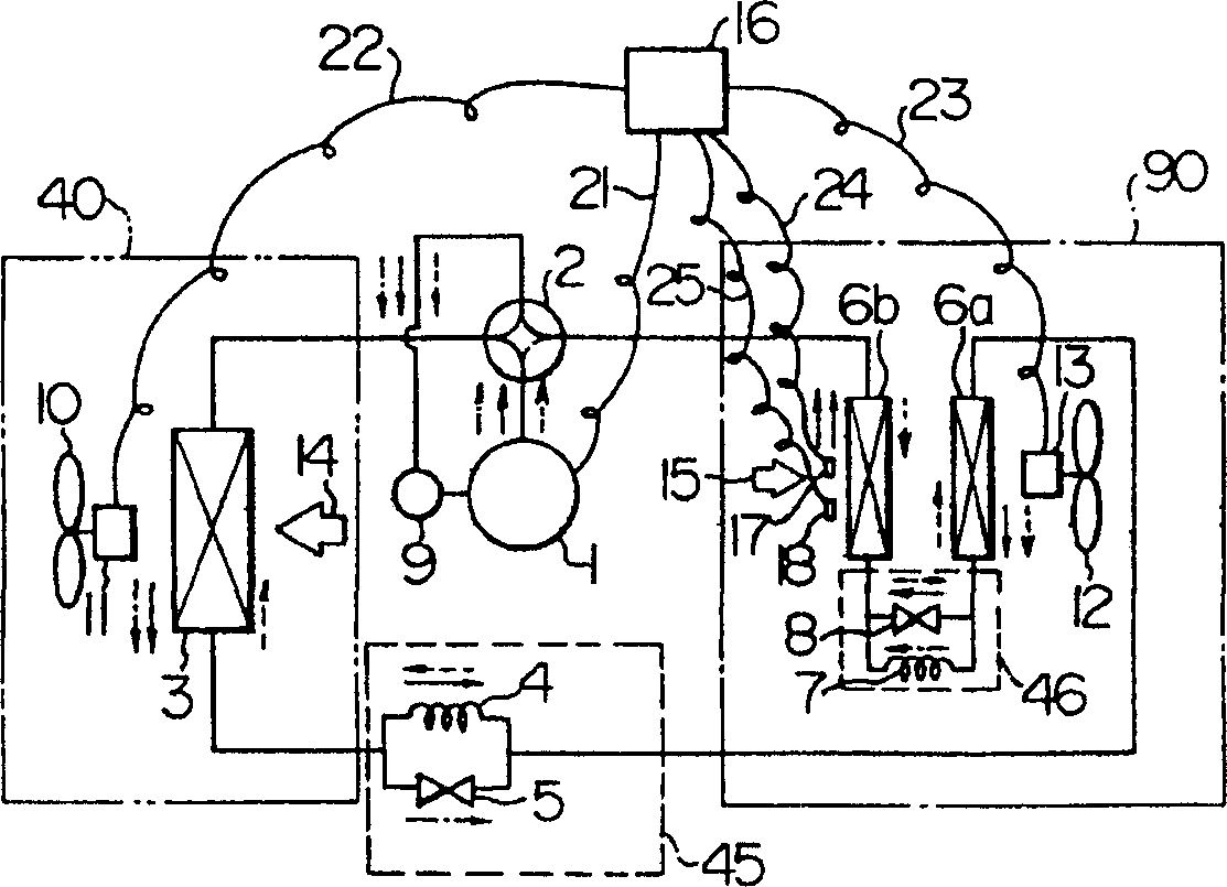
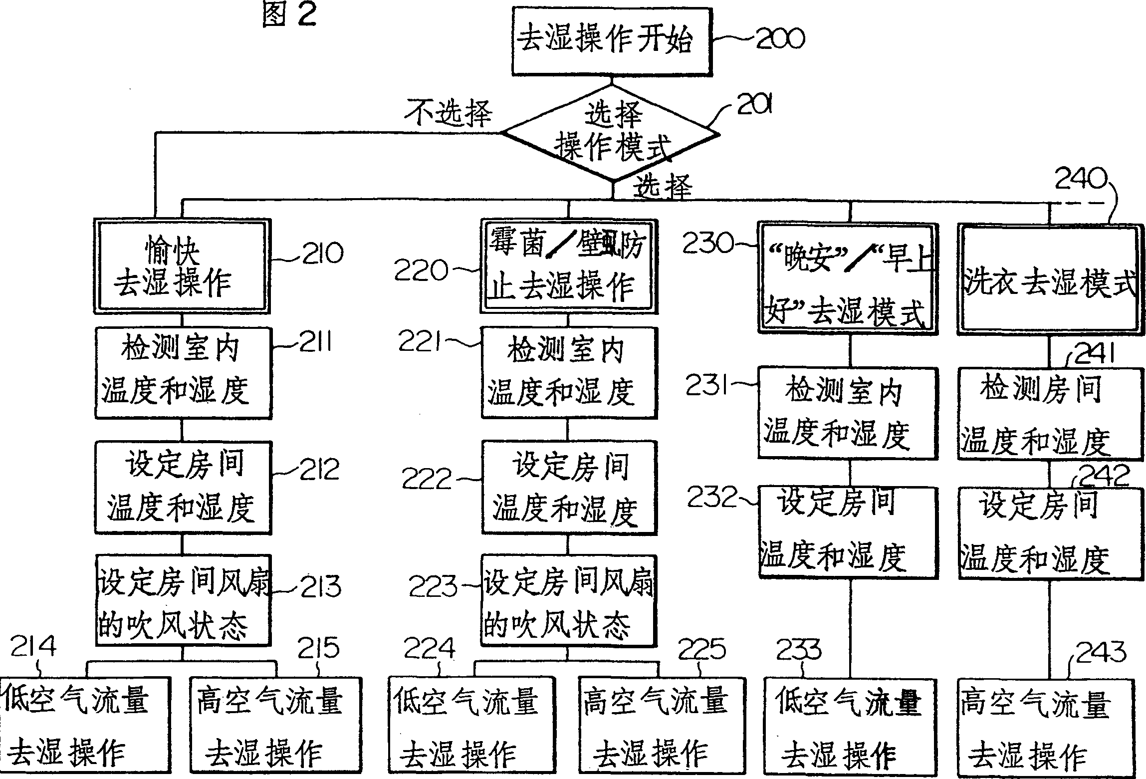
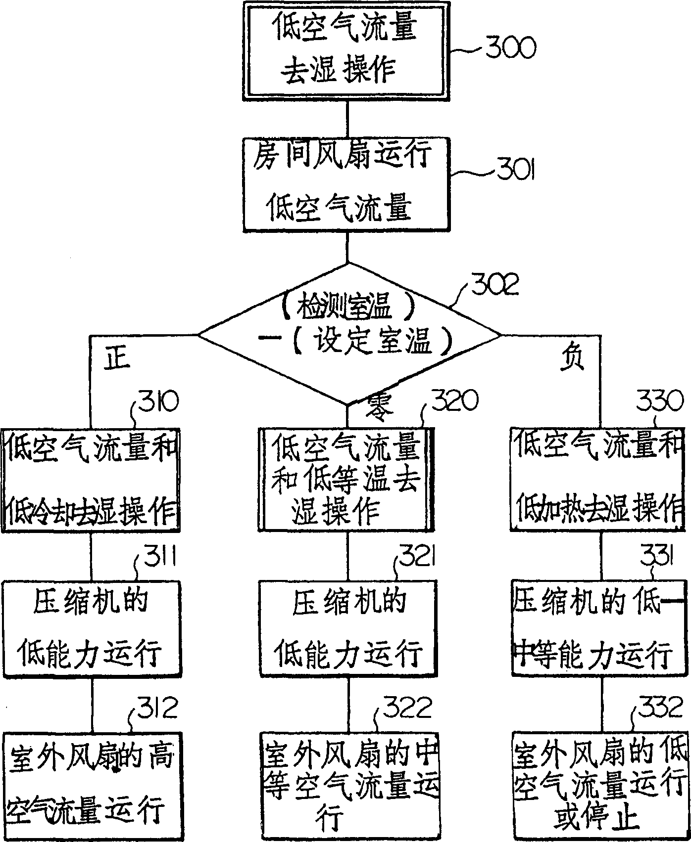
[0095] will combine Figure 1 to Figure 4 An embodiment of the present invention is described. figure 1 It is a schematic diagram of a refrigeration cycle and a control system; Fig. 2 is a flow chart of an operation mode; image 3 is a flowchart showing the method of operation for low air flow dehumidification operation; and Figure 4 is a flowchart of a method of high air flow dehumidification operation. The air conditioner according to the present embodiment is constituted as follows: figure 1 Among them, the reference number 1 represents the compressor; the reference number 2 represents a four-way valve, which is switched when switching the operating conditions such as cooling and heating; the reference number 3 represents the outdoor heat exchanger; The main restricto...


PUM


Abstract

An air conditioner comprises a compressor, a first indoor heat exchanger, a second indoor heat exchanger and a dehumidifying restricting device, which is connected between the first indoor heat exchanger and the second indoor heat exchanger, and used as a restricting device in the dehumidifying operation, wherein the airflow speed of an indoor fan used for ventilating the first indoor heat exchanger and the second indoor heat exchanger, is variable in the dehumidifying operation. The air conditioner comprises: a function of setting the indoor fan as a low air flow speed operation or a high air flow rate speed operation; and a function of operating the compressor with a higher capacity in the high air flow rate speed than in the low air flow speed operation.

Description

[0001] This application is a divisional application of the application dated June 1, 1994, application number 02131692.9, and titled "air-conditioning equipment". technical field [0002] The present invention relates to an air conditioner and its operating method. More particularly, the present invention relates to an air conditioner and its operating method in which dehumidification operation can be performed with little cooling to little heating over a wide temperature range. Background technique [0003] As a conventional air conditioner in which a dehumidification operation is performed to reduce humidity, there is known a system in which air cooled by an evaporator is reheated by an electric heater; Heat of condensation reheats. When comparing these two systems with each other, especially from the point of view of energy saving, the latter is considered to be better because the former consumes a lot of power. [0004] In addition, in Japanese Patent Unexamined Public...

Claims


Application Information

Patent Timeline
Patent Type & Authority Applications(China)
IPC IPC(8): F24F3/14F24F11/02
Inventor 中村启夫横山英范森本素生川村浩伸松尾一也小暮博志冈村哲信小曾户庄一
Owner HITACHI APPLIANCES INC
Why Eureka
Eureka Blog
Learn More