Top-mounted valve engine

A technology of overhead valves and engines, which is applied to the lubrication of engine components, machines/engines, and engines, and can solve problems such as low lubrication and easy wear

Active Publication Date: 2010-07-21
KUBOTA CORP
View PDF5 Cites 0 Cited by
  • Summary
  • Abstract
  • Description
  • Claims
  • Application Information

AI Technical Summary

Problems solved by technology

Therefore, they are less lubricated and prone to wear

Method used


Image

  • Top-mounted valve engine
  • Top-mounted valve engine
  • Top-mounted valve engine

Examples


Embodiment Construction

[0050] The present invention will be described below with reference to the accompanying drawings.

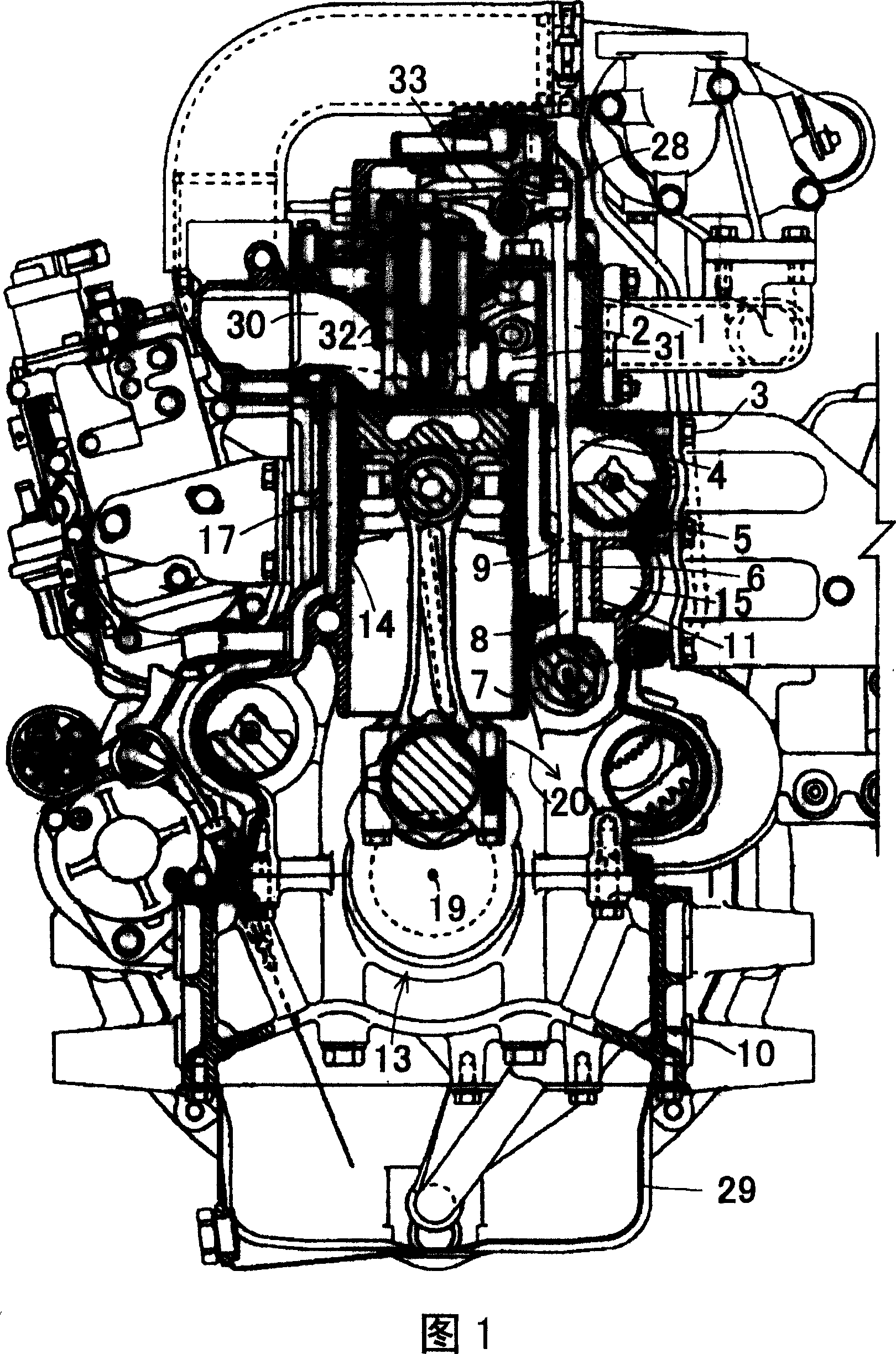
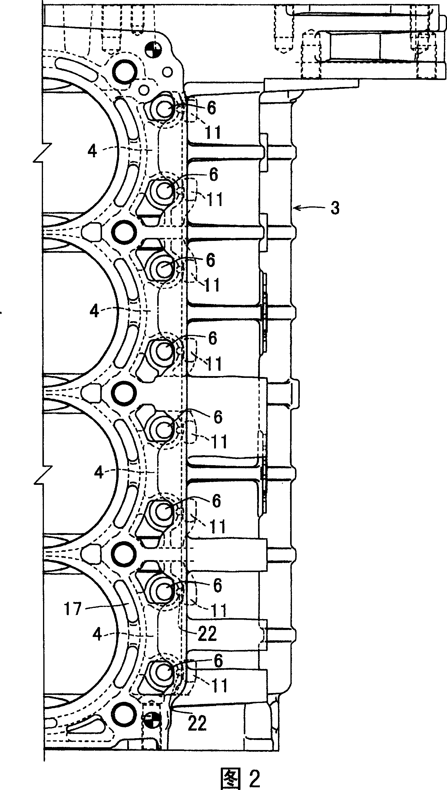
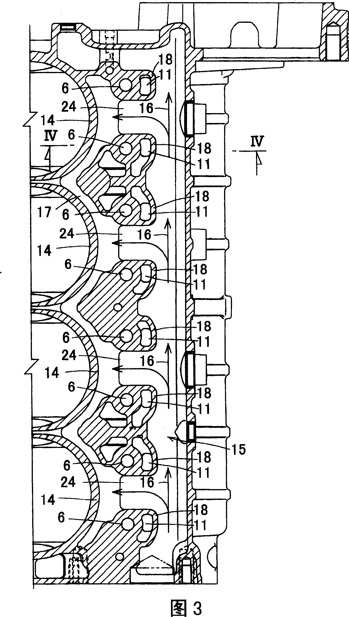
[0051] 1 to 4 show an overhead valve engine according to a first embodiment of the present invention. In this embodiment, a water-cooled multi-cylinder vertical overhead valve engine will be described.

[0052] The engine is outlined below:

[0053] As shown in FIG. 1 , the engine has a cylinder block 3 . The cylinder block 3 comprises an upper cylinder 14 and a lower crankcase 10, both forming a complete structure. The cylinder 14 is surrounded by a cylinder liner 17 . The cylinder head 1 is mounted on the top of the cylinder block 3 . A head cover 28 is mounted on the upper portion of the cylinder head 1 . An oil pan 29 is mounted on the lower portion of the crankcase 10 . The cylinder head 1 is formed with an intake port 30 and an exhaust port 31 . These port holes are opened and closed by intake valves 32 and exhaust valves (not shown). The intake valve 32 and the ex...


PUM


Abstract

To provide an overhead valve engine having improved lubricating performance between a valve cam and a tappet. In the overhead valve engine, a tappet guide hole 6 is provided downward from a bottom wall 5 of a push rod insertion chamber 4, the valve cam 7 is arranged on the lower side of the tappet guide hole 6 for guiding the tappet 8 placed on the valve cam 7 so as to be moved up and down via the tappet guide hole 6, a push rod 9 placed on the tappet 8 is serially inserted into the push rod insertion chamber 4 and a push rod insertion hole 2, and an oil flow-out hole 11 is provided in a range from the bottom wall 5 of the push rod insertion chamber 4 into a crank case 10. An outlet 11a of the oil flow-out hole 11 is opened to the upper side of the cam face of the valve cam 7 so that oil 12 flowing out of the outlet 11a of the oil flow-out hole 11 falls on the cam face of the valve cam 7.

Description

technical field [0001] The invention relates to an overhead valve engine, in particular to an overhead valve engine capable of improving the lubricating effect of a valve cam and a tappet. Background technique [0002] Examples of the conventional overhead valve engine and the present invention have a push rod insertion hole on the cylinder head and a push rod insertion chamber on the cylinder block. The push rod insertion hole communicates with the push rod insertion chamber. The push rod insertion chamber has a bottom wall from which the tappet guide hole is led downward. The valve cam is arranged under the guide hole of the tappet. The tappet guide hole guides the up and down movement of the tappet arranged on the valve cam. A push rod provided on the tappet is sequentially inserted through the push rod insertion chamber and the push rod insertion hole. The oil outlet hole is arranged from the bottom wall of the push rod insertion chamber to the inside of the crankcas...

Claims


Application Information

Patent Timeline
Patent Type & Authority Patents(China)
IPC IPC(8): F01M5/00
CPCF01M1/06
Inventor 岩永涉阿南裕之
Owner KUBOTA CORP
Why Eureka
Try Eureka