
Tube shaped electrical machine via non-electromagnetic force to release brake

A tubular motor, electromagnetic force technology, applied in the direction of electrical components, electromechanical devices, electric components, etc., can solve the problems of increased cost, short service life, many parts and so on, and achieve increased production cost, long service life and simple structure. Effect

Inactive Publication Date: 2006-02-22
HANGZHOU WISTAR MECHANICAL& ELECTRIC TECH CO LTD
View PDF2 Cites 14 Cited by
  • Summary
  • Abstract
  • Description
  • Claims
  • Application Information

AI Technical Summary

Problems solved by technology

This technical solution has many parts and components, the structure is very complicated, the cost is relatively high, and the coordination performance requirements between the various parts are high, so the processing is difficult, the overall reliability is poor, and the service life is short.

Method used


Image

  • Tube shaped electrical machine via non-electromagnetic force to release brake
  • Tube shaped electrical machine via non-electromagnetic force to release brake
  • Tube shaped electrical machine via non-electromagnetic force to release brake

Examples


Embodiment Construction

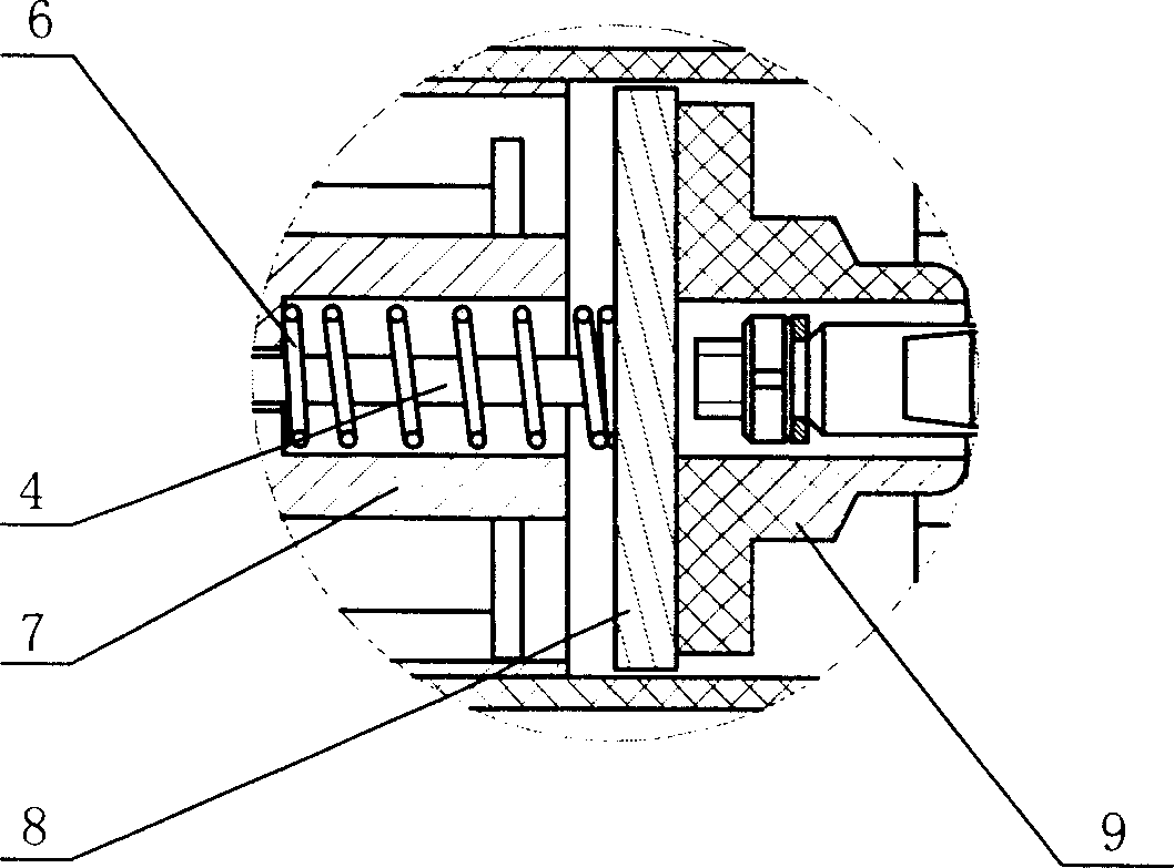
[0021] Such as figure 1 As shown, a tubular motor that can disengage the brake through non-electromagnetic force includes a mounting plate 1 for fixing to the wall, a machine base 2, a casing 3, and a drive motor 10 placed in the casing 3, a speed reduction device 11, Output shaft 12 and braking device, braking device comprises electromagnet 7, the spring 6 that is fixed on the electromagnet 7, the brake pad 8 that links to each other with spring 6 and the brake disc 9 corresponding with brake pad 8, drive motor 10 one end and brake disc 9 are matched and connected, and the other end is connected with the output shaft 12 through the reduction gear 11. The brake device is provided with a traction device, one end of the traction device passes through the electromagnet 7 and the spring 6 and is connected to the brake pad 8, and the other end leads out of the shell 3 of the tubular motor.

[0022] figure 1 , figure 2 Shown is an embodiment of the present invention. In this emb...


PUM


Abstract

The invention discloses a tubular motor which can separate the brake by non-electromagnetic force, comprising a mounting plate fixed on the wall, a engine base, a housing while a actuating motor, reduction apparatus, output shaft and a brake apparatus are mounted inside the housing. Wherein, the brake apparatus comprises a electromagnet, a spring mounted on the electromagnet, a brake block connected to the spring and a brake wheel relative to the brake block; one end of actuating motor meshes the brake wheel while another end meshes the output shaft via reduction apparatus; one end of draught device which is mounted on the brake apparatus is connected to the brake block while another end outward the housing of tubular motor. Said invention adds a draught device on the brake apparatus of tubular motor, which solves the problem of close door curtain when the power is out. The advantages of invention comprise simple structure, easy operation, long service life, and wide application without increased cost.

Description

technical field [0001] The invention relates to a tubular motor, in particular to a tubular motor capable of disengaging the brake through non-electromagnetic force. Background technique [0002] Tubular motor, a device that is fixed on doors and windows after being connected with a reel, and is used to store garage rolling gates, shutters, rolling shutters, awnings, projection screens and other equipment. It is generally composed of a drive motor, an output shaft, a deceleration device and a brake device. The brake device is generally composed of an electromagnet, a spring, a brake pad and a brake disc. Its working process in the electrified state is as follows: before the power is turned on, the The brake pad is frictionally engaged with the brake disc, the tubular motor is in the braking state, when the power supply of the tubular motor is turned on, the electromagnet in the brake device is energized to generate electromagnetic force, the brake pad is attracted by the ele...

Claims


Application Information

Patent Timeline
Patent Type & Authority Applications(China)
IPC IPC(8): H02K7/10H02K7/102
Inventor 狄剑军孙旭东孙旭华
Owner HANGZHOU WISTAR MECHANICAL& ELECTRIC TECH CO LTD
Learn More