
Optical regulator

An adjustment device, optical adjustment technology, applied to the adjustment device, the field shown in 2B of the present invention, can solve the problems of light refraction, image definition reduction, loss of overall image brightness, etc.

Inactive Publication Date: 2006-02-22
CORETRONIC
View PDF0 Cites 1 Cited by
  • Summary
  • Abstract
  • Description
  • Claims
  • Application Information

AI Technical Summary

Problems solved by technology

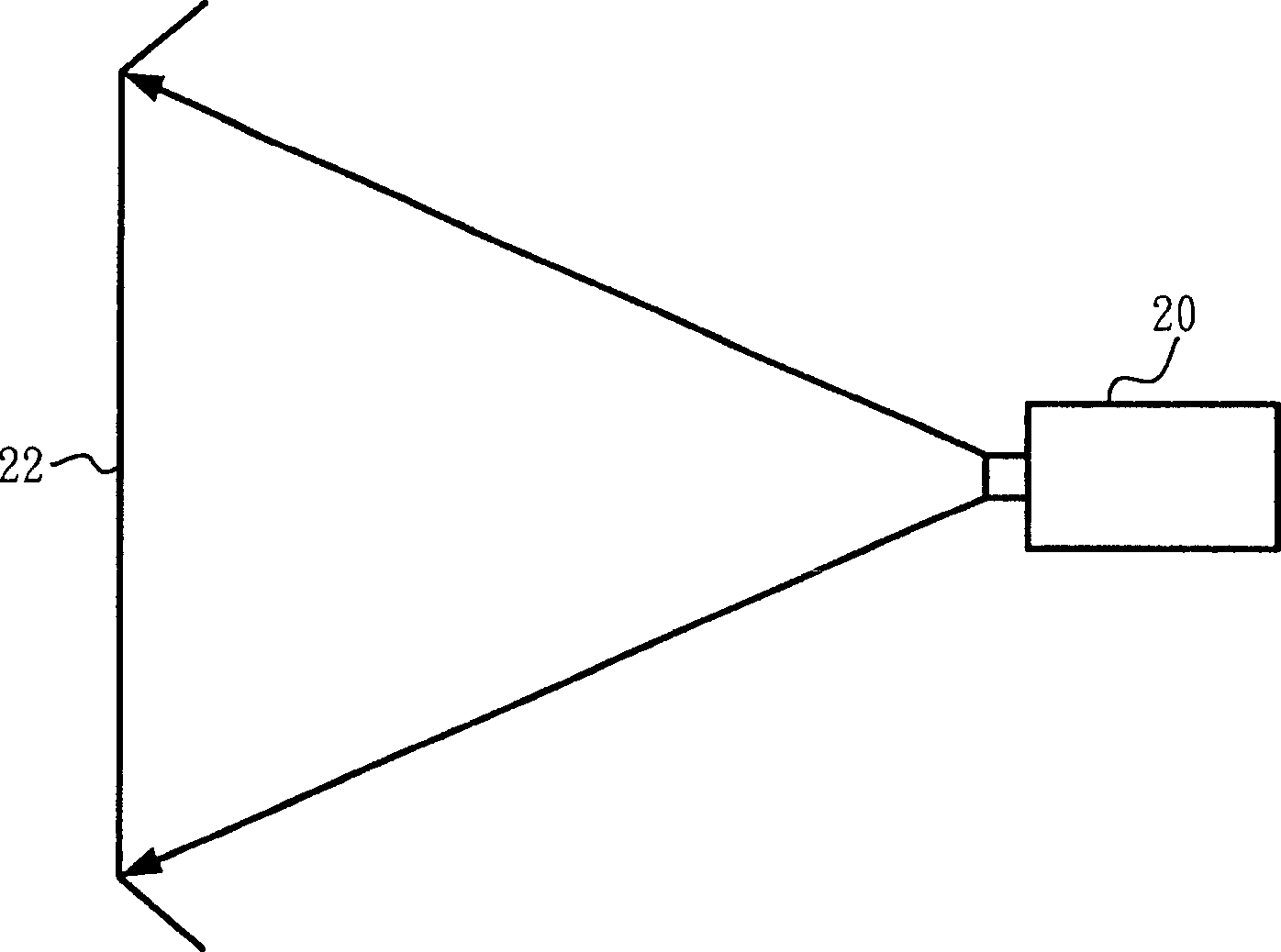
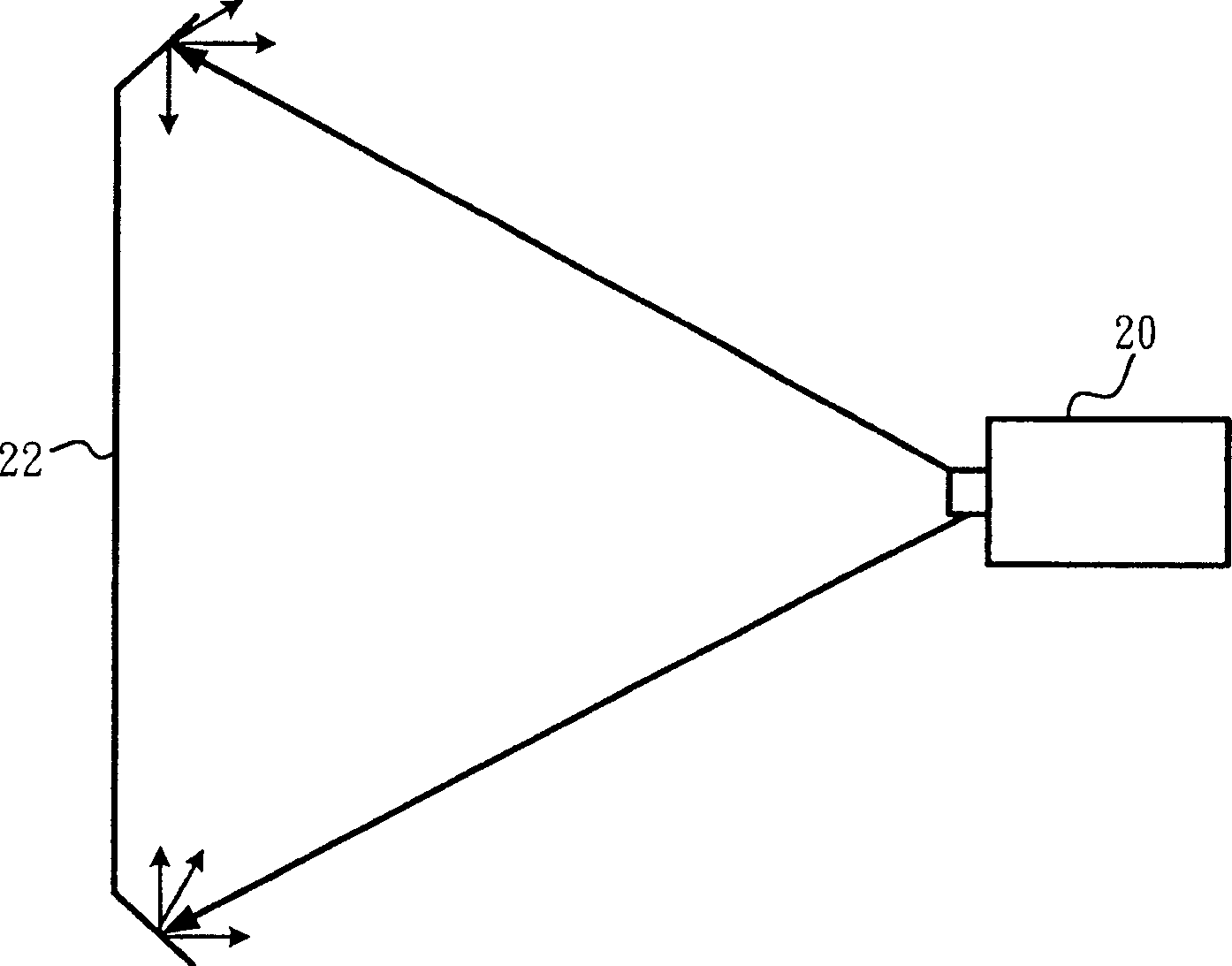
like Figure 2B As shown, when the lens 20 projects an enlarged image, the overall brightness will be beyond the range of the screen 22 and blocked by the screen so that the image cannot be projected outward. This will cause refraction of light, and then the overall brightness of the image will be lost, so it will be reduced. image clarity

Method used


Image

  • Optical regulator
  • Optical regulator
  • Optical regulator

Examples


Embodiment Construction

[0028] refer to image 3 and Figure 4 , image 3 It is a system block diagram of the adjusting device 30 of the present invention. Figure 4 It is a schematic diagram of the adjusting device 30 of the present invention. The present invention is an optical adjustment device 30 applied to an audio-visual playback system for adjusting the focal length of a lens group 32 in the audio-video playback system. The lens group 32 includes a first lens group 34 and a second lens group 36 . The adjusting device 30 includes a controller 38 and a moving device 40 .

[0029] The controller 38 is used for generating an adjustment signal. The moving device 40 is connected to the controller 38 and the lens group 32. The moving device 40 is used to adjust the positions of the first lens group 34 and the second lens group 36 according to the adjustment signal, thereby changing the focal length of the lens group 32 and the imaging of the lens group 32. focus.

[0030] refer to Figure 4 an...


PUM


Abstract

This invention provides one audio play system optic al adjusting device, which is to adjust the focus of one lens set in system, wherein, the lens set comprises one first lens set and one second lens set; the adjusting device comprises one controller to generate one adjusting signal and one movable device to connect to the controller and lens set and to adjust positions of first and second lens set according to signals to alternate the lens set focus and imaging focus.

Description

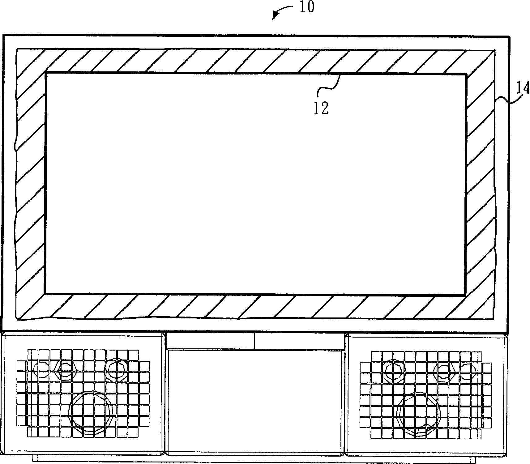
[0001] The technical field to which the invention belongs [0002] The invention relates to an adjustment device, in particular to an optical adjustment device applied to an audio-video playback system. Background technique [0003] The image projected by the current rear-projection TV, because the lens is in the form of a fixed focal length, the focal length of the lens cannot be changed, so there is no way to change the size of the image, so the current rear-projection TV does not have the function of zooming in or reducing the image. [0004] refer to figure 1 , figure 1 It is a schematic diagram of an image projected by a rear projection TV 10 in the known technology. Such as figure 1 As shown, because the edge of the image 14 projected by the rear projection TV 10 often has unstable interference signals, the image 14 is usually enlarged to make the image 14 larger than the size of the screen 12, and then the screen 12 is used to capture stable However, the general rea...

Claims


Application Information

Patent Timeline
Patent Type & Authority Applications(China)
IPC IPC(8): G02B7/02H04N5/74
Inventor 张根荣
Owner CORETRONIC
Learn More